
Reference Manual


PMAC-PCI Hardware Reference
PMAC-PCI E-Point Jumper Descriptions 25
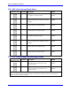
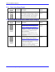
E111: Clock Lines Output Enable
E Point and
Physical
Layout
Location Description Default
E111
A7 Jump pin 1 to 2 to enable the PHASE, SERVO
and INIT lines on the J4 connector. Jump pin 2
to 3 to disable the PHASE, SERVO and INIT
lines on the J4 connector. E111 on positions 1
to 2 is necessary for daisy-chained PMACs
sharing the clock lines for synchronization.
2-3 Jumper
installed
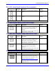
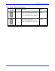
E114 - E115: Motors 5-8 Amplifier Enable Output Configure
E Point and
Physical
Layout
Location Description Default
E114
A3
CAUTION:
The jumper setting must match the type of
driver IC, or damage to the IC will result.
Jump pin 1 to 2 to apply A+15V/A+V (as set
by E100) to pin 10 of U53 AENAn & EQUn
driver IC (should be ULN2803A for sink
output configuration).
Jump pin 2 to 3 to apply GND to pin 10 of
U53 (should be UDN2981A for source output
configuration).
1-2 Jumper
installed
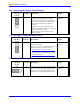
E115
A3
CAUTION:
The jumper setting must match the type of
driver IC, or damage to the IC will result.
Jump pin 1 to 2 to apply GND to pin 10 of
U53 AENAn & EQUn (should be ULN2803A
for sink output configuration).
Jump pin 2 to 3 to apply A+15V/A+V (as set
by E100) to pin 10 of U53 (should be
UDN2981A for source output configuration).
1-2 Jumper
installed