
Reference Manual


PMAC-PCI Hardware Reference
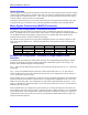
24 PMAC-PCI E-Point Jumper Descriptions
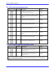
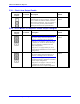
E101 - E102: Motors 1-4 Amplifier Enable Output Configure
E Point and
Physical
Layout
Location Description Default
E101
A3
CAUTION:
The jumper setting must match the type of
driver IC, or damage to the IC will result.
Jump pin 1 to 2 to apply A+15V/A+V (as set
by E100) to pin 10 of "U37" AENAn & EQUn
driver IC (should be ULN2803A for sink
output configuration).
Jump pin 2 to 3 to apply GND to pin 10 of U37
(should be UDN2981A for source output
configuration).
1-2 Jumper
installed
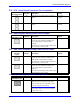
E102
A3
CAUTION:
The jumper setting must match the type of
driver IC, or damage to the IC will result
Jump pin 1 to 2 to apply GND to pin 10 of U37
AENAn & EQUn (should be ULN2803A for
sink output configuration).
Jump pin 2 to 3 to apply A+15V/A+V (as set
by E100) to pin 10 of U37 (should be
UDN2981A for source output configuration).
1-2 Jumper
installed
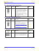
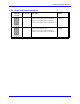
E109: Reserved for Future Use
E Point and
Physical
Layout
Location Description Default
E109
B6 For future use. No jumper
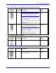
E110: Serial Port Configure
E Point and
Physical
Layout
Location Description Default
E110
A7 Jump pin 1 to 2 for use of the J4 connector as
RS-232. Jump pin 2 to 3 for use of the J4
connector as RS-422.
1-2 Jumper
installed