
Reference Manual


PMAC-PCI Hardware Reference
PMAC-PCI E-Point Jumper Descriptions 23
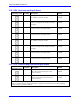
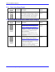
E90: Host-Supplied Switch Pull-Up Enable
E Point and
Physical
Layout
Location Description Default
E90
B5 Jump pin 1 to 2 to use A+15V from J8 pin 59
as supply for input flags (E89 ON) {flags
should be tied to AGND} or A+15V/OPT+V
from J7 pin 59 as supply for input flags (E89
OFF) {flags should be tied to separate 0V
reference}.
Jump pin 2 to 3 to use +12V from PC bus
connector P1-pin B09 as supply for input flags
{flags should be tied to GND}.
See also E85, E87, E88 and PMAC Opto-
isolation diagram
1-2 Jumper
installed
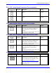
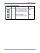
E98: DAC/ADC Clock Frequency Control
E Point and
Physical
Layout
Location Description Default
E98
A4 Jump 1-2 to provide a 2.45 MHz DCLK signal
to DACs and ADCs.
Jump 2-3 to provide a 1.22 MHz DCLK signal
to DACs and ADCs. Important for high
accuracy A/D conversion on Acc-28.
Note:
This also divides the phase and servo clock
frequencies in half.
See E29-E33, E3-E6, I10
1-2 Jumper
installed
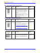
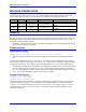
E100: Output Flag Supply Select
E Point and
Physical
Layout
Location Description Default
E100
A3 Jump pin 1 to 2 to apply analog supply voltage
A+15V to U37 and U53 flag output driver IC.
Jump pin 2 to 3 to apply flag supply voltage
OPT+V to U37 and U53 flag output driver IC.
1-2 Jumper
installed