
Reference Manual


PMAC-PCI Hardware Reference
22 PMAC-PCI E-Point Jumper Descriptions
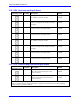
E74 - E75: Clock Output Control for Ext. Interpolation
E Point and
Physical Layout
Location Description Default
E74
B9 Jump pin 1 to 2 to allow SCLK/ to output on
CHC4/.
No jumper
installed
E75
B9 Jump pin 1 to 2 to allow SCLK to output on
CHC4.
No jumper
installed
Note: SCLK out permits synchronous latching of analog encoder interpolators such as Acc-8D Opt 8.
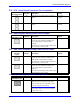
E85: Host-Supplied Analog Power Source Enable
E Point and
Physical Layout
Location Description Default
E85
C5 Jump pin 1 to pin 2 to allow A+14V to come
from PC bus (ties amplifier and PMAC PCI
power supply together. Defeats OPTO
coupling.)
Note that if E85 is changed, E88 and E87 must
also be changed. Also, see E90.
No jumper
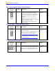
E87 - E88: Host-Supplied Analog Power Source Enable
E Point and
Physical
Layout
Location Description Default
E87
C5 Jump pin 1 to pin 2 to allow AGND to come
from PC bus (ties amplifier and PMAC PCI
GND together. Defeats OPTO coupling.)
Note that if E87 is changed, E85 and E88 must
also be changed. Also, see E90.
No jumper
E88
B2 Jump pin 1 to pin 2 to allow A-14V to come
from PC bus (ties amplifier and PMAC PCI
power supply together. Defeats OPTO
coupling.)
Note that if E88 is changed; E87 and E85 must
also be changed. Also, see E90.
No jumper
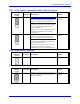
E89: Amplifier-Supplied Switch Pull-Up Enable
E Point and
Physical Layout
Location Description
Default
E89
B5 Jump pin 1 to 2 to use A+15V on J8
(JMACH1) pin 59 as supply for input flags.
Remove jumper to use A+15V/OPT+V from
J7 pin 59 as supply for input flags.
Note:
This jumper setting is only relevant if E90
connects pin 1 to 2.
Jumper installed