
Reference Manual


PMAC-PCI Hardware Reference
PMAC-PCI E-Point Jumper Descriptions 15
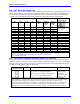
E3 - E6: Servo Clock Frequency Control
The servo clock (which determines how often the servo loop is closed) is derived from the phase clock
(see E98, E29 - E33) through a divide-by-N counter. Jumpers E3 through E6 control this dividing
function.
E3 E4 E5 E6 Servo Clock = Phase Clock
Divided by N
Default and Physical Layout
E3 E4 E5 E6
Location A4 A4 A4 A4
ON ON ON ON N = divided by 1
OFF ON ON ON N = divided by 2
ON OFF ON ON N = divided by 3
OFF OFF ON ON N = divided by 4 Only E5 and E6 on
ON OFF ON ON N = divided by 5
OFF ON OFF ON N = divided by 6
ON OFF OFF ON N = divided by 7
OFF OFF OFF ON N = divided by 8
ON ON ON OFF N = divided by 9
OFF ON ON OFF N = divided by 10
ON OFF ON OFF N = divided by 11
OFF OFF ON OFF N = divided by 12
ON ON OFF OFF N = divided by 13
OFF ON OFF OFF N = divided by 14
ON OFF OFF OFF N = divided by 15
OFF OFF OFF OFF N = divided by 16
Note: The setting of I-variable I10 should be adjusted to match the servo interrupt cycle time set by E98,
E3 -- E6, E29 -- E33, and the crystal clock frequency. I10 holds the length of a servo interrupt cycle,
scaled so that 8,388,608 equals one millisecond. Since I10 has a maximum value of 8,388,607, the servo
interrupt cycle time should always be less than a millisecond (unless you want to make your basic unit of
time on PMAC something other than a millisecond). If you wish a servo sample time greater than one
millisecond, the sampling may be slowed in software with variable Ix60.
Frequency can be checked on J4 pins 21 & 22. It can also be checked from software by typing RX:0 in
the PMAC terminal at 10-second intervals and dividing the difference of successive responses by 10000.
The resulting number is the approximate Servo Clock frequency kHz.
Note: If E40-E43 are not all on, the phase clock is received from an external source through the J4 serial-
port connector, and the settings of E3 – E6 are not relevant.
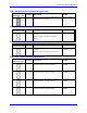
E7: Machine Input Source/Sink Control
E Point and
Physical Layout
Location Description Default
E7
A6 Jump pin 1 to 2 to apply +5V to input
reference resistor sip pack; this will bias MI1
to MI8 inputs to +5V for OFF state; input
must then be grounded for on state.
Jump pin 2 to 3 to apply GND to input
reference resistor sip pack; this will bias MI1
to MI8 inputs to GND for OFF state; input
must then be pulled up for on state (+5V to
+24V).
1-2 Jumper
installed