
Reference Manual


PMAC-PCI Hardware Reference
PMAC-PCI E-Point Jumper Descriptions 13
E-POINT DESCRIPTIONS
CPU Board E-Point Descriptions
The following jumper descriptions are for the PMAC CPU part number 602705-107.
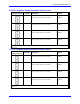
E1: Watchdog Disable Jumper
E Point and
Physical Layout
Description Default
E1
Jump pin 1 to 2 to disable Watchdog timer (for test purposes only).
Remove jumper to enable Watchdog timer.
No Jumper
E2: DPRAM Location Configure
E Point and
Physical Layout
Description Default
E2
Jump pin 1 to 2 to access the dual-ported RAM on baseboard.
Jump pin 2 to 3 to access the dual-ported RAM through JEXP
expansion port.
Jumper connects
pins 1 and 2
Note: Jumper E2 is present on –108 and newer boards only. Older versions could access DPRAM from either
source without a jumper configuration, but with less robust buffering.
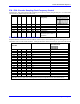
E4 – E6: Power-Up/Reset Load Source
E Point and
Physical Layout
Description Default
E4
E6
Remove jumper E4; jump E5 pin 1 to 2; jump E6
pin 1 to 2 to read flash IC on power-up/reset.
No E4 jumper installed;
E5 and E6 jump pin 1 to 2.
Note: Other combinations are for factory use only; the board will not operate in any other configuration
E7: Firmware Reload Enable
E Point and
Physical Layout
Description Default
E7
Jump pin 1 to 2 to reload firmware through serial
or bus port.
Remove jumper for normal operation.
No jumper installed