
Reference Manual
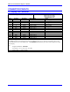
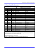
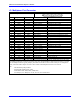
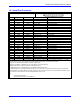
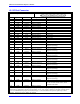
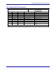
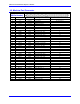

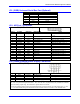
Table Of Contents
- Base Version
- Option 2: Dual-Ported RAM
- Option 5xF: CPU Speed Options
- Option 6: Extended Servo Algorithm Firmware
- Option 6L: Special Lookahead Firmware
- Option 10: Firmware Version Specification
- Option 12: Analog-to-Digital Converters
- Option 15: V-to-F Converter for Analog Input
- Option 16: Battery-Backed Parameter Memory
- Digital Power Supply
- Analog Power Supply
- Resistor Pack Configuration: Flag and Digital Inputs Voltage Selection
- Types of Overtravel Limits
- Home Switches
- Incremental Encoder Connection
- DAC Output Signals
- Amplifier Enable Signal (AENAx/DIRn)
- Amplifier Fault Signal (FAULTn)
- Command Inputs
- Selector Inputs
- Alternate Use
- Reset Input
- Handwheel Inputs
- Optional Voltage to Frequency Converter
- J1 - Display Port (JDISP Port)
- J2 - Control-Panel Port (JPAN Port)
- J3 - Thumbwheel Multiplexer Port (JTHW Port)
- J4 - Serial Port (JRS422 Port)
- J5 - General-Purpose Digital Inputs and Outputs (JOPTO Port)
- J6 – Expansion Port \(JXIO Port\)
- J8 - Machine Connectors (JMACH Port)
- J9 – Compare Equal Outputs Port \(JEQU Port\)
- J17 - Serial Port (JRS232 Port)
- J30 – Optional Analog to Digital Inputs \(JANA P
- J31 – Optional Universal Serial Bus Port \(JUSB
- JS1 – Expansion Ports \(JS1 Port\)
- TB1 – Power Supply Terminal Block \(JPWR Connect
- LED Indicators
- Fuse
- J1 (JDISP)/Display
- J2 (JPAN)/Control Panel
- J3 (JTHW)/Multiplexer Port
- J4 (JRS422)/RS232 OR 422/Serial Communications
- J5 (JOPT)/OPTO I/O
- J6 (JXIO)/Expansion Board
- J8 (JMACH)/Machine Connector
- JS1/A-D Inputs 1-4
- JEQU/Position Compare
- JANA/Analog Inputs Option
PMAC PCI Lite Hardware Reference Manual
Connector Pinouts
53
J9 (JEQU): Position-Compare Connector
J9 JEQU (10-Pin Connector)
Front View
Pin # Symbol Function Description Notes
1 EQU1/ Output Enc. 1 comp-EQ Low is true
2 EQU2/ Output Enc. 2 comp-EQ Low is true
3 EQU3/ Output Enc. 3 comp-EQ Low is true
4 EQU4/ Output Enc. 4 comp-EQ Low is true
5 EQU5/ Output Amp enable 1 Low is true
6 EQU6/ Output Amp enable 2 Low is true
7 EQU7/ Output Amp enable 3 Low is true
8 EQU8/ Output Amp enable 4 Low is true
9 A+V Supply Positive supply +5v to +24v
10 AGND Common Analog ground
This connector provides the position-compare outputs and the amplifier enable outputs for the four servo interface
channels. The board is equipped with a ULN2803A or equivalent open-collector driver IC on U37. It may be
replaced with UDN2891A or equivalent open-emitter driver (E101-E102 must be changed), or a 74ACT563 or
equivalent 5V CMOS driver.
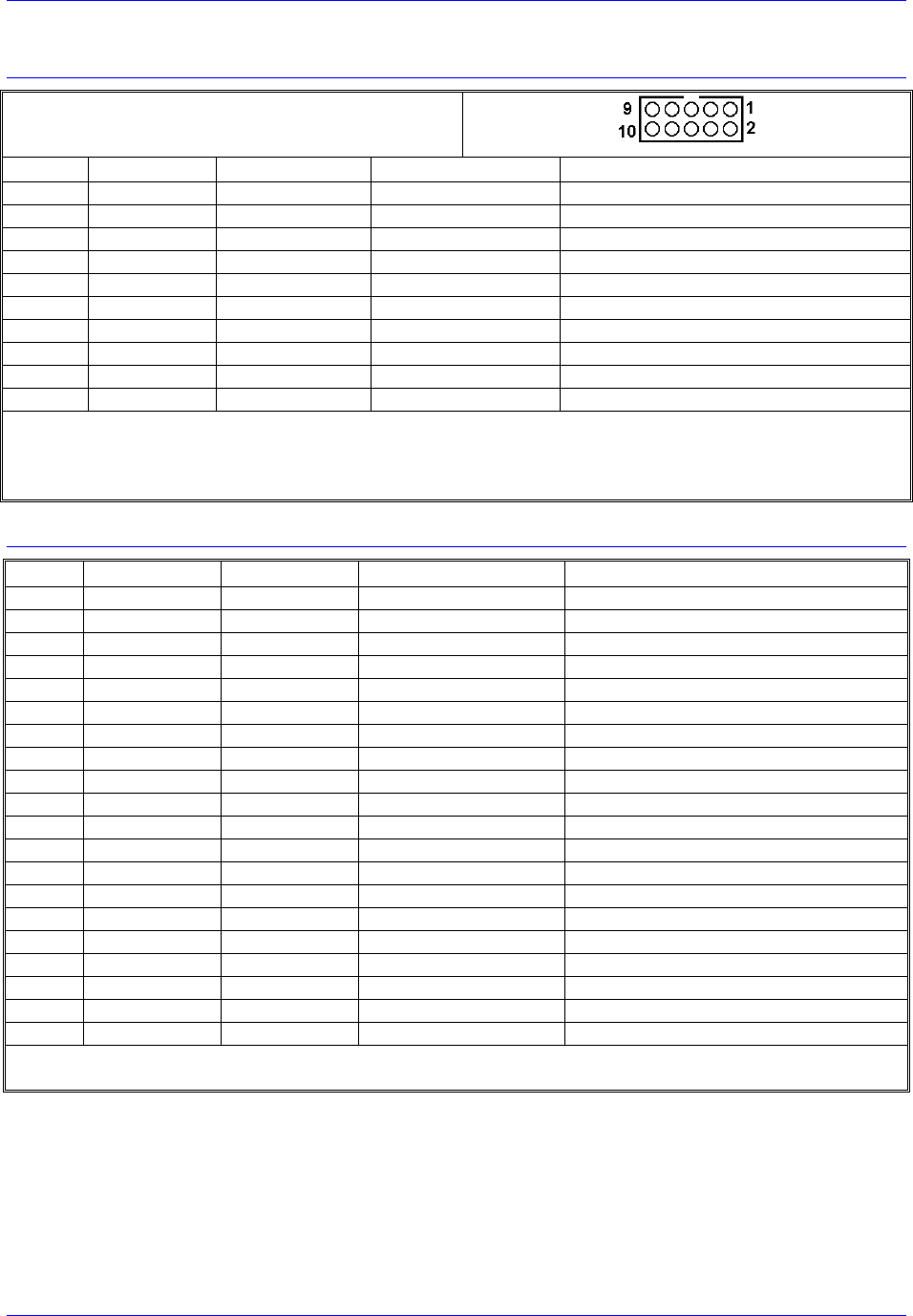
J30 (JANA) Analog Input Port Connector (Optional)
Pin # Symbol Function Description Notes
1 ANAI00 Input Analog input 0 0-5v or +/-2.5v range
2 ANAI01 Input Analog input 1 0-5v or +/-2.5v range
3 ANAI02 Input Analog input 2 0-5v or +/-2.5v range
4 ANAI03 Input Analog input 3 0-5v or +/-2.5v range
5 ANAI04 Input Analog input 4 0-5v or +/-2.5v range
6 ANAI05 Input Analog input 5 0-5v or +/-2.5v range
7 ANAI06 Input Analog input 6 0-5v or +/-2.5v range
8 ANAI07 Input Analog input 7 0-5v or +/-2.5v range
9 ANAI08 Input Analog input 8 0-5v or +/-2.5v range
1
10 ANAI09 Input Analog input 9 0-5v or +/-2.5v range
1
11 ANAI10 Input Analog input 10 0-5v or +/-2.5v range
1
12 ANAI11 Input Analog input 11 0-5v or +/-2.5v range
1
13 ANAI12 Input Analog input 12 0-5v or +/-2.5v range
1
14 ANAI13 Input Analog input 13 0-5v or +/-2.5v range
1
15 ANAI14 Input Analog input 14 0-5v or +/-2.5v range
1
16 ANAI15 Input Analog input 15 0-5v or +/-2.5v range
1
17 GND Common PMAC common Not isolated from digital
18 +12V Output Pos. supply voltage To power external circuitry
19 GND Common PMAC common Not isolated from digital
20 -12V Output Neg. supply voltage To power external circuitry
The JANA connector provides the inputs for the eight or 16 optional analog inputs on the PMAC2.
1
Only present if Option-12A ordered.