
Reference Manual

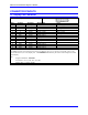
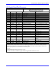
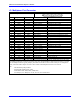
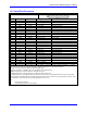
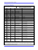
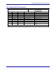
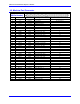
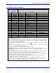
Table Of Contents
- Base Version
- Option 2: Dual-Ported RAM
- Option 5xF: CPU Speed Options
- Option 6: Extended Servo Algorithm Firmware
- Option 6L: Special Lookahead Firmware
- Option 10: Firmware Version Specification
- Option 12: Analog-to-Digital Converters
- Option 15: V-to-F Converter for Analog Input
- Option 16: Battery-Backed Parameter Memory
- Digital Power Supply
- Analog Power Supply
- Resistor Pack Configuration: Flag and Digital Inputs Voltage Selection
- Types of Overtravel Limits
- Home Switches
- Incremental Encoder Connection
- DAC Output Signals
- Amplifier Enable Signal (AENAx/DIRn)
- Amplifier Fault Signal (FAULTn)
- Command Inputs
- Selector Inputs
- Alternate Use
- Reset Input
- Handwheel Inputs
- Optional Voltage to Frequency Converter
- J1 - Display Port (JDISP Port)
- J2 - Control-Panel Port (JPAN Port)
- J3 - Thumbwheel Multiplexer Port (JTHW Port)
- J4 - Serial Port (JRS422 Port)
- J5 - General-Purpose Digital Inputs and Outputs (JOPTO Port)
- J6 – Expansion Port \(JXIO Port\)
- J8 - Machine Connectors (JMACH Port)
- J9 – Compare Equal Outputs Port \(JEQU Port\)
- J17 - Serial Port (JRS232 Port)
- J30 – Optional Analog to Digital Inputs \(JANA P
- J31 – Optional Universal Serial Bus Port \(JUSB
- JS1 – Expansion Ports \(JS1 Port\)
- TB1 – Power Supply Terminal Block \(JPWR Connect
- LED Indicators
- Fuse
- J1 (JDISP)/Display
- J2 (JPAN)/Control Panel
- J3 (JTHW)/Multiplexer Port
- J4 (JRS422)/RS232 OR 422/Serial Communications
- J5 (JOPT)/OPTO I/O
- J6 (JXIO)/Expansion Board
- J8 (JMACH)/Machine Connector
- JS1/A-D Inputs 1-4
- JEQU/Position Compare
- JANA/Analog Inputs Option

PMAC PCI-Lite Hardware Reference Manual
52 Connector Pinouts
J8: Machine Port Connector
J8 JMACH
(60-Pin Header)
Continued
Front View
Pin # Symbol Function Description Notes
40 -LIM4 Input Pos End Limit 4 8,9
41 HMFL3 Input Home-Flag 3 10
42 HMFL4 Input Home-Flag 4 10
43 DAC1 Output Ana. Out Pos. 1 4
44 DAC2 Output Ana. Out Pos. 2 4
45 DAC1/ Output Ana. Out Neg. 1 4,5
46 DAC2/ Output Ana. Out Neg. 2 4,5
47 AENA1/DIR1 Output Amp-ENA/Dir. 1 6
48 AENA2/DIR2 Output Amp-ENA/Dir. 2 6
49 FAULT1 Input Amp-Fault 1 7
50 FAULT2 Input Amp-Fault 2 7
51 +LIM1 Input Neg End Limit 1 8,9
52 +LIM2 Input Neg End Limit 2 8,9
53 -LIM1 Input Pos End Limit 1 8,9
54 -LIM2 Input Pos End Limit 2 8,9
55 HMFL1 Input Home-Flag 1 10
56 HMFL2 Input Home-Flag 2 10
57 FEFCO/ Output FE/Watchdog Out Indicator/Driver
58 AGND Input Analog Common
59 A+15V/OPT+V Input Analog +15v Supply
60 A-15V Input Analog -15v Supply
The J8 connector is used to connect PMAC to the first four channels (Channels 1, 2, 3, and 4) of servo
amps, flags, and encoders.
Note 1: In standalone applications, these lines can be used as +5V power supply inputs to power PMAC's
digital circuitry. However, if a terminal block is available on a version of PMAC, it is preferable to bring
the +5V power in through the terminal block.
Note 2: Referenced to digital common (GND). Maximum of +
12V permitted between this signal and its
complement.
Note 3: Leave this input floating if not used (i.e., digital single-ended encoders). In this case, jumper (E18
- 21, E24 - 27) for channel should hold input at 2.5V.
Note 4: +
10V, 10mA max, referenced to analog common (AGND).
Note 5: Leave floating if not used. Do not tie to AGND. In this case, AGND is the return line.
Note 6: Functional polarity controlled by jumper(s) E17. Choice between AENA and DIR use controlled
by Ix02 and Ix25.
Note 7: Functional polarity controlled by variable Ix25. Must be conducting to 0V (usually AGND) to
produce a '0' in PMAC software. Automatic fault function can be disabled with Ix25.
Note 8: Pins marked -LIMn should be connected to switches at the positive end of travel. Pins marked
+LIMn should be connected to switches at the negative end of travel.
Note 9: Must be conducting to 0V (usually AGND) for PMAC to consider itself not into this limit.
Automatic limit function can be disabled with Ix25.
Note 10: Functional polarity for homing or other trigger use of HMFLn controlled by Encoder/Flag
Variable 2 (I902, I907, etc.) HMFLn selected for trigger by Encoder/Flag Variable 3 (I903, I908, etc.).
Must be conducting to 0V (usually AGND) to produce a '0' in PMAC software.