
Reference Manual

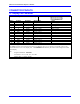
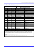
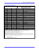
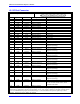
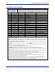
Table Of Contents
- Base Version
- Option 2: Dual-Ported RAM
- Option 5xF: CPU Speed Options
- Option 6: Extended Servo Algorithm Firmware
- Option 6L: Special Lookahead Firmware
- Option 10: Firmware Version Specification
- Option 12: Analog-to-Digital Converters
- Option 15: V-to-F Converter for Analog Input
- Option 16: Battery-Backed Parameter Memory
- Digital Power Supply
- Analog Power Supply
- Resistor Pack Configuration: Flag and Digital Inputs Voltage Selection
- Types of Overtravel Limits
- Home Switches
- Incremental Encoder Connection
- DAC Output Signals
- Amplifier Enable Signal (AENAx/DIRn)
- Amplifier Fault Signal (FAULTn)
- Command Inputs
- Selector Inputs
- Alternate Use
- Reset Input
- Handwheel Inputs
- Optional Voltage to Frequency Converter
- J1 - Display Port (JDISP Port)
- J2 - Control-Panel Port (JPAN Port)
- J3 - Thumbwheel Multiplexer Port (JTHW Port)
- J4 - Serial Port (JRS422 Port)
- J5 - General-Purpose Digital Inputs and Outputs (JOPTO Port)
- J6 – Expansion Port \(JXIO Port\)
- J8 - Machine Connectors (JMACH Port)
- J9 – Compare Equal Outputs Port \(JEQU Port\)
- J17 - Serial Port (JRS232 Port)
- J30 – Optional Analog to Digital Inputs \(JANA P
- J31 – Optional Universal Serial Bus Port \(JUSB
- JS1 – Expansion Ports \(JS1 Port\)
- TB1 – Power Supply Terminal Block \(JPWR Connect
- LED Indicators
- Fuse
- J1 (JDISP)/Display
- J2 (JPAN)/Control Panel
- J3 (JTHW)/Multiplexer Port
- J4 (JRS422)/RS232 OR 422/Serial Communications
- J5 (JOPT)/OPTO I/O
- J6 (JXIO)/Expansion Board
- J8 (JMACH)/Machine Connector
- JS1/A-D Inputs 1-4
- JEQU/Position Compare
- JANA/Analog Inputs Option
PMAC PCI Lite Hardware Reference Manual
Connector Pinouts
49
J5: I/O Port Connector
J5 JOPT (34-Pin Connector)
Front View
Pin # Symbol Function Description Notes
1 MI8 Input Machine Input 8 Low is true
2 GND Common PMAC Common
3 MI7 Input Machine Input 7 Low is true
4 GND Common PMAC Common
5 MI6 Input Machine Input 6 Low is true
6 GND Common PMAC Common
7 MI5 Input Machine Input 5 Low is true
8 GND Common PMAC Common
9 MI4 Input Machine Input 4 Low is true
10 GND Common PMAC Common
11 MI3 Input Machine Input 3 Low is true
12 GND Common PMAC Common
13 MI2 Input Machine Input 2 Low is true
14 GND Common PMAC Common
15 MI1 Input Machine Input 1 Low is true
16 GND Common PMAC Common
17 MO8 Output Machine Output 8 Low-true (sinking);
High-true (sourcing)
18 GND Common PMAC Common
19 MO7 Output Machine Output 7 Low-true (sinking);
High-true (sourcing)
20 GND Common PMAC Common
21 MO6 Output Machine Output 6 Low-true (sinking);
High-true (sourcing)
22 GND Common PMAC Common
23 MO5 Output Machine Output 5 Low-true (sinking);
High-true (sourcing)
24 GND Common PMAC Common
25 MO4 Output Machine Output 4 Low-true (sinking);
High-true (sourcing)
26 GND Common PMAC Common
27 MO3 Output Machine Output 3 Low-true (sinking);
High-true (sourcing)
28 GND Common PMAC Common
29 MO2 Output Machine Output 2 Low-true (sinking);
High-true (sourcing)
30 GND Common PMAC Common
31 MO1 Output Machine Output 1 Low-true (sinking);
High-true (sourcing)
32 GND Common PMAC Common
33 +V Input/Output +V Power I/O (+V = +5v to +24v) +5v out from PMAC, +5
to +24v in from external source, diode
isolation from PMAC
34 GND Common PMAC Common
This connector provides means for eight general-purpose inputs and eight general-purpose outputs. Inputs and
outputs may be configured to accept or provide either +5V or +24V signals. Outputs can be made sourcing with an
IC (U13 to UDN2981) and jumper (E1 and E2) change. E7 controls whether the inputs are pulled up or down
internally. Outputs are rated at 100mA per channel.