
Reference Manual

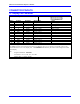
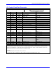
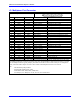
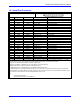
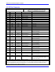
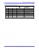
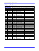
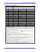
Table Of Contents
- Base Version
- Option 2: Dual-Ported RAM
- Option 5xF: CPU Speed Options
- Option 6: Extended Servo Algorithm Firmware
- Option 6L: Special Lookahead Firmware
- Option 10: Firmware Version Specification
- Option 12: Analog-to-Digital Converters
- Option 15: V-to-F Converter for Analog Input
- Option 16: Battery-Backed Parameter Memory
- Digital Power Supply
- Analog Power Supply
- Resistor Pack Configuration: Flag and Digital Inputs Voltage Selection
- Types of Overtravel Limits
- Home Switches
- Incremental Encoder Connection
- DAC Output Signals
- Amplifier Enable Signal (AENAx/DIRn)
- Amplifier Fault Signal (FAULTn)
- Command Inputs
- Selector Inputs
- Alternate Use
- Reset Input
- Handwheel Inputs
- Optional Voltage to Frequency Converter
- J1 - Display Port (JDISP Port)
- J2 - Control-Panel Port (JPAN Port)
- J3 - Thumbwheel Multiplexer Port (JTHW Port)
- J4 - Serial Port (JRS422 Port)
- J5 - General-Purpose Digital Inputs and Outputs (JOPTO Port)
- J6 – Expansion Port \(JXIO Port\)
- J8 - Machine Connectors (JMACH Port)
- J9 – Compare Equal Outputs Port \(JEQU Port\)
- J17 - Serial Port (JRS232 Port)
- J30 – Optional Analog to Digital Inputs \(JANA P
- J31 – Optional Universal Serial Bus Port \(JUSB
- JS1 – Expansion Ports \(JS1 Port\)
- TB1 – Power Supply Terminal Block \(JPWR Connect
- LED Indicators
- Fuse
- J1 (JDISP)/Display
- J2 (JPAN)/Control Panel
- J3 (JTHW)/Multiplexer Port
- J4 (JRS422)/RS232 OR 422/Serial Communications
- J5 (JOPT)/OPTO I/O
- J6 (JXIO)/Expansion Board
- J8 (JMACH)/Machine Connector
- JS1/A-D Inputs 1-4
- JEQU/Position Compare
- JANA/Analog Inputs Option

PMAC PCI-Lite Hardware Reference Manual
48 Connector Pinouts
J4: Serial Port Connector
J4 JRS422 (26-Pin Connector)
Front View
Pin # Symbol Function Description Notes
1 CHASSI Common PMAC Common
2 S+5V Output +5Vdc Supply Deactivated by E8
3 RD- Input Receive data Diff. I/O low true **
4 RD+ Input Receive data Diff. I/O high true *
5 SD- Output Send data Diff. I/O low true **
6 SD+ Output Send data Diff. I/O high true *
7 CS+ Input Clear to send Diff. I/O high true **
8 CS- Input Clear to send Diff. I/O low true *
9 RS+ Output Req. To send Diff. I/O high true **
10 RS- Output Req. To send Diff. I/O low true *
11 DTR Bidirect Data term read Tied to DSR
12 INIT/ Input PMAC Reset Low is reset
13 GND Common PMAC Common **
14 DSR Bidirect Data Set Ready Tied to DTR
15 SDIO- Bidirect Special Data Diff. I/O low true
16 SDIO+ Bidirect Special Data Diff. I/O high true
17 SCIO- Bidirect Special Ctrl. Diff. I/O low true
18 SCIO+ Bidirect Special Ctrl. Diff. I/O high true
19 SCK- Bidirect Special Clock Diff. I/O low true
20 SCK+ Bidirect Special Clock Diff. I/O high true
21 SERVO- Bidirect Servo Clock Diff. I/O low true ***
22 SERVO+ Bidirect Servo Clock Diff. I/O high true ***
23 PHASE- Bidirect Phase Clock Diff. I/O low true ***
24 PHASE+ Bidirect Phase Clock Diff. I/O high true ***
25 GND Common PMAC Common
26 +5V Output +5Vdc Supply Power supply out
The JRS422 connector provides the PMAC with the ability to communicate both in RS422 and RS232. In addition,
this connector is used to daisy chain interconnect multiple PMACs for synchronized operation.
Jumper E110 selects between RS232 or RS422 signal types.
Jumper E110 enables or disables the use of the Phase, Servo and Init lines.
* Note: Required for communications to an RS422 host port.
** Note: Required for communications to an RS422 or RS232 host port.
*** Note: Output on card with E40-E43 all ON. Input on card with any of E40-E43 OFF. These pins permit full
synchronization of multiple PMACs through sharing of phase and servo clocks. If synchronization is desired, these
lines should be connected even if serial communications is not used.
See:
Serial Communications
Synchronizing PMAC to other PMACs