
Reference Manual
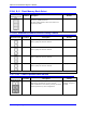
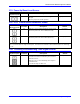
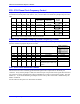
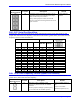
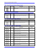
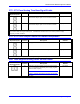
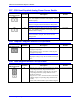
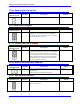

Table Of Contents
- Base Version
- Option 2: Dual-Ported RAM
- Option 5xF: CPU Speed Options
- Option 6: Extended Servo Algorithm Firmware
- Option 6L: Special Lookahead Firmware
- Option 10: Firmware Version Specification
- Option 12: Analog-to-Digital Converters
- Option 15: V-to-F Converter for Analog Input
- Option 16: Battery-Backed Parameter Memory
- Digital Power Supply
- Analog Power Supply
- Resistor Pack Configuration: Flag and Digital Inputs Voltage Selection
- Types of Overtravel Limits
- Home Switches
- Incremental Encoder Connection
- DAC Output Signals
- Amplifier Enable Signal (AENAx/DIRn)
- Amplifier Fault Signal (FAULTn)
- Command Inputs
- Selector Inputs
- Alternate Use
- Reset Input
- Handwheel Inputs
- Optional Voltage to Frequency Converter
- J1 - Display Port (JDISP Port)
- J2 - Control-Panel Port (JPAN Port)
- J3 - Thumbwheel Multiplexer Port (JTHW Port)
- J4 - Serial Port (JRS422 Port)
- J5 - General-Purpose Digital Inputs and Outputs (JOPTO Port)
- J6 – Expansion Port \(JXIO Port\)
- J8 - Machine Connectors (JMACH Port)
- J9 – Compare Equal Outputs Port \(JEQU Port\)
- J17 - Serial Port (JRS232 Port)
- J30 – Optional Analog to Digital Inputs \(JANA P
- J31 – Optional Universal Serial Bus Port \(JUSB
- JS1 – Expansion Ports \(JS1 Port\)
- TB1 – Power Supply Terminal Block \(JPWR Connect
- LED Indicators
- Fuse
- J1 (JDISP)/Display
- J2 (JPAN)/Control Panel
- J3 (JTHW)/Multiplexer Port
- J4 (JRS422)/RS232 OR 422/Serial Communications
- J5 (JOPT)/OPTO I/O
- J6 (JXIO)/Expansion Board
- J8 (JMACH)/Machine Connector
- JS1/A-D Inputs 1-4
- JEQU/Position Compare
- JANA/Analog Inputs Option
PMAC PCI-Lite Hardware Reference Manual
36 E-Point Jumper Descriptions
E Point and
Physical Layout
Location Description Default
E40
E43
B5 Install all of these jumpers for the card to use its
internally generated clock signals and to output
these on the serial port connector.
If any of these jumpers is OFF, the card will
expect to input these clock signals from the serial
port connector.
Jumpers E40-E43
installed
E44 - E47: Serial Port Baud Rate
Jumpers E44 - E47 control the baud rate for serial communications if the saved value of I46 is 0 and
jumper E48 controls the CPU frequency. If the saved value of I46 is greater than 0, I46 controls the CPU
frequency and I54 controls the baud rate.
Baud Rate Control E Points Baud Rate
Default and
Physical Layout
E44 E45 E46 E47 I46=0
E48 OFF
I46=0
E48 ON
E44 E45 E46 E47
Loc. B5 B5 C5 C5
On On On On Disabled Disabled
Off On On On 600 900
On Off On On 800* 1200
Off Off On On 1200 1800
On On Off On 1600* 2400
Off On Off On 2400 3600
On Off Off On 3200* 4800
Off Off Off On 4800 7200
On On On Off 6400* 9600
Off On On Off 9600 14400
On Off On Off 12800* 19200
Off Off On Off 19200 28800
On On Off Off 25600* 38400
Off On Off Off 38400 57600
On Off Off Off 51200* 76800
Off Off Off Off 76800 115200
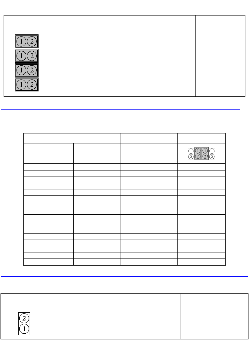
E48: CPU Clock Frequency Control (Option CPU Section)
E48 controls the CPU clock frequency only if the saved value of I46 is 0. If the saved value of I46 is
greater than 0, I46 controls the CPU frequency.
E Point and
Physical Layout
Location Description Default
E48
C5 Jump pins 1 and 2 to multiply crystal
frequency by three inside CPU for 60MHz
operation.
Remove jumper to multiply crystal frequency
by two inside CPU for 40 MHz operation.
Jumper installed (Option 5,
5B)
Jumper not installed
(Standard, Option 4A, 5A)