
Reference Manual
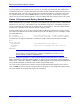

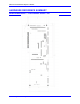
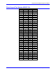
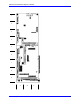

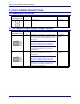
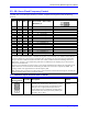
Table Of Contents
- Base Version
- Option 2: Dual-Ported RAM
- Option 5xF: CPU Speed Options
- Option 6: Extended Servo Algorithm Firmware
- Option 6L: Special Lookahead Firmware
- Option 10: Firmware Version Specification
- Option 12: Analog-to-Digital Converters
- Option 15: V-to-F Converter for Analog Input
- Option 16: Battery-Backed Parameter Memory
- Digital Power Supply
- Analog Power Supply
- Resistor Pack Configuration: Flag and Digital Inputs Voltage Selection
- Types of Overtravel Limits
- Home Switches
- Incremental Encoder Connection
- DAC Output Signals
- Amplifier Enable Signal (AENAx/DIRn)
- Amplifier Fault Signal (FAULTn)
- Command Inputs
- Selector Inputs
- Alternate Use
- Reset Input
- Handwheel Inputs
- Optional Voltage to Frequency Converter
- J1 - Display Port (JDISP Port)
- J2 - Control-Panel Port (JPAN Port)
- J3 - Thumbwheel Multiplexer Port (JTHW Port)
- J4 - Serial Port (JRS422 Port)
- J5 - General-Purpose Digital Inputs and Outputs (JOPTO Port)
- J6 – Expansion Port \(JXIO Port\)
- J8 - Machine Connectors (JMACH Port)
- J9 – Compare Equal Outputs Port \(JEQU Port\)
- J17 - Serial Port (JRS232 Port)
- J30 – Optional Analog to Digital Inputs \(JANA P
- J31 – Optional Universal Serial Bus Port \(JUSB
- JS1 – Expansion Ports \(JS1 Port\)
- TB1 – Power Supply Terminal Block \(JPWR Connect
- LED Indicators
- Fuse
- J1 (JDISP)/Display
- J2 (JPAN)/Control Panel
- J3 (JTHW)/Multiplexer Port
- J4 (JRS422)/RS232 OR 422/Serial Communications
- J5 (JOPT)/OPTO I/O
- J6 (JXIO)/Expansion Board
- J8 (JMACH)/Machine Connector
- JS1/A-D Inputs 1-4
- JEQU/Position Compare
- JANA/Analog Inputs Option
PMAC PCI Lite Hardware Reference Manual
E-Point Jumper Descriptions 31
E-POINT JUMPER DESCRIPTIONS
E0: Reserved for Future Use
E Point and
Physical Layout
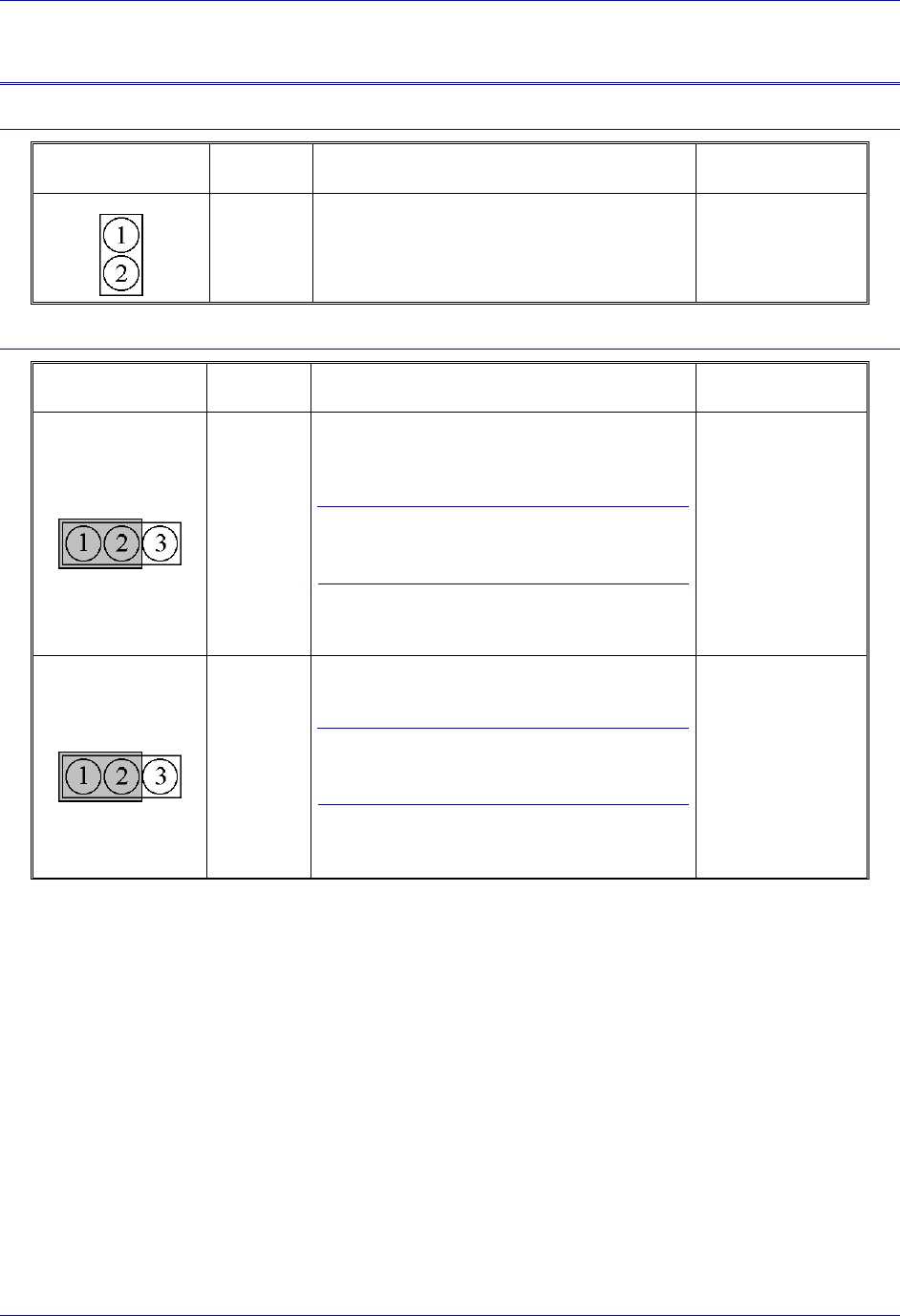
Location Description Default
E0
A5 For future use. No jumper
E1 - E2: Machine Output Supply Voltage Configure
E Point and
Physical Layout
Location Description Default
E1
A5 Jump pin 1 to 2 to apply +V (+5V to 24V) to
pin 10 of U13 (should be ULN2803A for sink
output configuration) JOPTO Machine outputs
M01-M08.
Caution:
The jumper setting must match the type of
driver IC, or damage to the IC will result.
Jump pin 2 to 3 to apply GND to pin 10 of U13
(should be UDN2981A for source output
configuration).
1-2 Jumper
installed
E2
A5 Jump pin 1 to 2 to apply GND to pin 10 of U13
(should be ULN2803A for sink output
configuration).
Caution:
The jumper setting must match the type of
driver IC, or damage to the IC will result.
Jump pin 2 to 3 to apply +V (+5V to 24V) to
pin 10 of U13 (should be UDN2981A for
source output configuration).
1-2 Jumper
installed