
Reference Manual

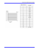
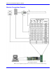

Table Of Contents
- Base Version
- Option 2: Dual-Ported RAM
- Option 5xF: CPU Speed Options
- Option 6: Extended Servo Algorithm Firmware
- Option 6L: Special Lookahead Firmware
- Option 10: Firmware Version Specification
- Option 12: Analog-to-Digital Converters
- Option 15: V-to-F Converter for Analog Input
- Option 16: Battery-Backed Parameter Memory
- Digital Power Supply
- Analog Power Supply
- Resistor Pack Configuration: Flag and Digital Inputs Voltage Selection
- Types of Overtravel Limits
- Home Switches
- Incremental Encoder Connection
- DAC Output Signals
- Amplifier Enable Signal (AENAx/DIRn)
- Amplifier Fault Signal (FAULTn)
- Command Inputs
- Selector Inputs
- Alternate Use
- Reset Input
- Handwheel Inputs
- Optional Voltage to Frequency Converter
- J1 - Display Port (JDISP Port)
- J2 - Control-Panel Port (JPAN Port)
- J3 - Thumbwheel Multiplexer Port (JTHW Port)
- J4 - Serial Port (JRS422 Port)
- J5 - General-Purpose Digital Inputs and Outputs (JOPTO Port)
- J6 – Expansion Port \(JXIO Port\)
- J8 - Machine Connectors (JMACH Port)
- J9 – Compare Equal Outputs Port \(JEQU Port\)
- J17 - Serial Port (JRS232 Port)
- J30 – Optional Analog to Digital Inputs \(JANA P
- J31 – Optional Universal Serial Bus Port \(JUSB
- JS1 – Expansion Ports \(JS1 Port\)
- TB1 – Power Supply Terminal Block \(JPWR Connect
- LED Indicators
- Fuse
- J1 (JDISP)/Display
- J2 (JPAN)/Control Panel
- J3 (JTHW)/Multiplexer Port
- J4 (JRS422)/RS232 OR 422/Serial Communications
- J5 (JOPT)/OPTO I/O
- J6 (JXIO)/Expansion Board
- J8 (JMACH)/Machine Connector
- JS1/A-D Inputs 1-4
- JEQU/Position Compare
- JANA/Analog Inputs Option

PMAC PCI Lite Hardware Reference Manual
Software Setup 21
SOFTWARE SETUP
Note:
The PMAC PCI Lite requires the use of V1.17 or newer firmware. There are few
differences between the previous V1.16H firmware and the V1.17 firmware other
than the addition of internal support for the Flex CPU design.
Communications
Delta Tau provides communication tools that take advantage of the PCI bus Plug and Play feature of 32-
bits Windows
®
based computers. With Pewin 32 Pro, a PMAC PCI Lite board plugged in a PCI bus slot
will be recognized by the operating system when the computer is booted up. The available PCI address,
dual-ported RAM address and Interrupt lines are set automatically by the operating system and can be
checked (but not modified) in the resources page of the device manager.
PMAC I-Variables
PMAC has a large set of Initialization parameters (I-variables) that determine the personality of the card
for a specific application. Many of these are used to configure a motor properly. Once set up, these
variables may be stored in non-volatile EAROM memory (using the SAVE command) so the card is
always configured properly (PMAC loads the EAROM I-variable values into RAM on power-up).
The easiest way to program, set up and troubleshoot PMAC is by using the PMAC Executive Program
Pewin and its related add-on packages P1Setup and PMAC Plot. These software packages are available
by ordering Acc-9WN.
The programming features and configuration variables for the PMAC are fully described in the
PMAC User and Software manuals.
Operational Frequency and Baud Rate Setup
Note:
Older PMAC boards required a start-up PLC for setting the operational frequency
at 80 MHz. This method is not compatible with the PMAC PCI Lite board and
when used will shut it down.
The operational frequency of the CPU is set in software by the PMAC I46 I- variable. If this variable is
set to 0, PMAC firmware looks at the jumper E48 to set the operational frequency. If I46 is set to a value
greater than 0, the operational frequency is set to 10MHz * (I46 + 1), regardless of the jumper setting. If
the desired operational frequency is higher than the maximum rated frequency for that CPU, the
operational frequency will be reduced to the rated maximum. It is possible to operate the Flex CPU board
at a frequency below its rated maximum. I46 is used only at power-up/reset. To change the operational
frequency, set a new value of I46, issue a SAVE command to store this value in non-volatile flash
memory. Then issue a $$$ command to reset the controller.
To determine the frequency, at which the CPU is actually operating, issue the TYPE command to the
PMAC. The PMAC will respond with five data items, the last of which is CLK Xn, in which n is the
multiplication factor from the 20MHz crystal frequency (not 10MHz). n should be equivalent to
(I46+1)/2 if I46 is not requesting a frequency greater than the maximum rated for that CPU board. n will
be 2 for 40MHz operation, 4 for 80MHz operation, and 8 for 160MHz operation.