
Reference Manual

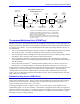
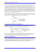
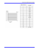
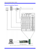

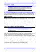
Table Of Contents
- Base Version
- Option 2: Dual-Ported RAM
- Option 5xF: CPU Speed Options
- Option 6: Extended Servo Algorithm Firmware
- Option 6L: Special Lookahead Firmware
- Option 10: Firmware Version Specification
- Option 12: Analog-to-Digital Converters
- Option 15: V-to-F Converter for Analog Input
- Option 16: Battery-Backed Parameter Memory
- Digital Power Supply
- Analog Power Supply
- Resistor Pack Configuration: Flag and Digital Inputs Voltage Selection
- Types of Overtravel Limits
- Home Switches
- Incremental Encoder Connection
- DAC Output Signals
- Amplifier Enable Signal (AENAx/DIRn)
- Amplifier Fault Signal (FAULTn)
- Command Inputs
- Selector Inputs
- Alternate Use
- Reset Input
- Handwheel Inputs
- Optional Voltage to Frequency Converter
- J1 - Display Port (JDISP Port)
- J2 - Control-Panel Port (JPAN Port)
- J3 - Thumbwheel Multiplexer Port (JTHW Port)
- J4 - Serial Port (JRS422 Port)
- J5 - General-Purpose Digital Inputs and Outputs (JOPTO Port)
- J6 – Expansion Port \(JXIO Port\)
- J8 - Machine Connectors (JMACH Port)
- J9 – Compare Equal Outputs Port \(JEQU Port\)
- J17 - Serial Port (JRS232 Port)
- J30 – Optional Analog to Digital Inputs \(JANA P
- J31 – Optional Universal Serial Bus Port \(JUSB
- JS1 – Expansion Ports \(JS1 Port\)
- TB1 – Power Supply Terminal Block \(JPWR Connect
- LED Indicators
- Fuse
- J1 (JDISP)/Display
- J2 (JPAN)/Control Panel
- J3 (JTHW)/Multiplexer Port
- J4 (JRS422)/RS232 OR 422/Serial Communications
- J5 (JOPT)/OPTO I/O
- J6 (JXIO)/Expansion Board
- J8 (JMACH)/Machine Connector
- JS1/A-D Inputs 1-4
- JEQU/Position Compare
- JANA/Analog Inputs Option
PMAC PCI-Lite Hardware Reference Manual
16 Machine Connections
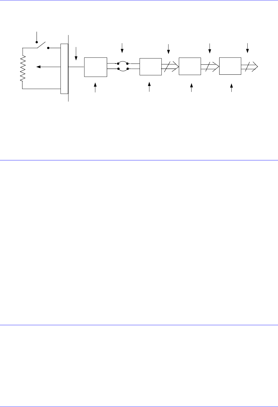
(Optional user
provided +10V)
Hardware Voltage-to-
Frequency Converter
Software-Configured
Hardware Counter
Software
Interpolation
Pulse Train
0 to 250 KHz
Integer
Count
+5V
J2
25
20
26
-5Kohm
Wiper
GND
Voltage
0 to +10V
V/F
25 KHz/V
E73
(E24:1-2)
I915=4
E72
CHA4
CHA4/
24
X:$C00C+
Y:$723=$00C00C
X:$723
24
24
Interpolated
Count
Value
Proportional
to Voltage
ENC4
Decoder/
Counter
1/T
Encoder
Conversion
“Time
Base”
Conversion
Software
Differentiation
X:$729
Y:$728=$400723
Y:$729=Scaling
To use this value for feedrate override for a coordinate system, set the
time base source address I-Variable (Ix93 for C.S.x.) to 1833 ($729).
To use this value for some other purpose, assign an M-Variable to this
register (e.g., M60->X:$729,0-24-,U).
Scaling is set by the value in Y:$729 (for the default conversion table).
This value can be determined interactively by varying the input voltage
and noting the effect.
Using PMAC’s Control Panel
Analog (Wiper) Input
Thumbwheel Multiplexer Port (JTHW Port)
The Thumbwheel Multiplexer Port, or Multiplexer Port, on the JTHW (J3) connector has eight input lines
and eight output lines. The output lines can be used to multiplex large numbers of inputs and outputs on
the port, and Delta Tau provides accessory boards and software structures (special M-variable definitions)
to capitalize on this feature. Up to 32 of the multiplexed I/O boards may be daisychained on the port, in
any combination.
• The Acc-18 Thumbwheel Multiplexer board provides up to 16 BCD thumbwheel digits or 64 discrete
TTL inputs per board. The TWD and TWB forms of M-variables are used for this board.
• The Acc-34x family Serial I/O Multiplexer boards provides 64 I/O point per board, optically isolated
from PMAC. The TWS form of M-variables is used for these boards.
• The Acc-8D Option 7 Resolver-to-Digital Converter board provides up to four resolver channels
whose absolute positions can be read through the thumbwheel port. The TWR form of M-variables is
used for this board.
• The Acc-8D Option 9 Yaskawa
TM
Absolute Encoder Interface board can connect to up to four of
these encoders. The absolute position is read serially through the multiplexer port on power up.
If none of these accessory boards is used, the inputs and outputs on this port may be used as discrete, non-
multiplexed I/O. They map into PMAC’s processor space at Y address $FFC1. The suggested M-
variable definitions for this use are M40 to M47 for the eight outputs, and M50 to M57 for the eight
inputs. The Acc-27 Optically Isolated I/O board buffers the I/O in this non-multiplexed form, with each
point rated to 24V and 100mA.
Optional Analog Inputs (JANA Port)
The JANA port is present only if Option 12 is ordered for the PMAC. Option 12 provides eight 12-bit
analog inputs (ANAI00-ANAI07). Option 12A provides eight additional 12-bit analog inputs (ANA08-
ANAI15) for a total of 16 inputs. The analog inputs can be used as unipolar inputs in the 0V to +5V
range, or bi-polar inputs in the -2.5V to +2.5V range.
The analog-to-digital converters on PMAC require +5V and -12V supplies. These supplies are not
isolated from digital +5V circuitry on PMAC. If the PMAC is plugged into the PCI bus, the supplies are
taken from the bus power supply. In a standalone application, the supplies must be brought in on terminal
block TB1. The -12V and matching +12V supply voltages are available on the J30 connector to supply
the analog circuitry providing the signals.