
Reference Manual

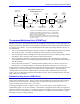
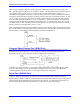

Table Of Contents
- Base Version
- Option 2: Dual-Ported RAM
- Option 5xF: CPU Speed Options
- Option 6: Extended Servo Algorithm Firmware
- Option 6L: Special Lookahead Firmware
- Option 10: Firmware Version Specification
- Option 12: Analog-to-Digital Converters
- Option 15: V-to-F Converter for Analog Input
- Option 16: Battery-Backed Parameter Memory
- Digital Power Supply
- Analog Power Supply
- Resistor Pack Configuration: Flag and Digital Inputs Voltage Selection
- Types of Overtravel Limits
- Home Switches
- Incremental Encoder Connection
- DAC Output Signals
- Amplifier Enable Signal (AENAx/DIRn)
- Amplifier Fault Signal (FAULTn)
- Command Inputs
- Selector Inputs
- Alternate Use
- Reset Input
- Handwheel Inputs
- Optional Voltage to Frequency Converter
- J1 - Display Port (JDISP Port)
- J2 - Control-Panel Port (JPAN Port)
- J3 - Thumbwheel Multiplexer Port (JTHW Port)
- J4 - Serial Port (JRS422 Port)
- J5 - General-Purpose Digital Inputs and Outputs (JOPTO Port)
- J6 – Expansion Port \(JXIO Port\)
- J8 - Machine Connectors (JMACH Port)
- J9 – Compare Equal Outputs Port \(JEQU Port\)
- J17 - Serial Port (JRS232 Port)
- J30 – Optional Analog to Digital Inputs \(JANA P
- J31 – Optional Universal Serial Bus Port \(JUSB
- JS1 – Expansion Ports \(JS1 Port\)
- TB1 – Power Supply Terminal Block \(JPWR Connect
- LED Indicators
- Fuse
- J1 (JDISP)/Display
- J2 (JPAN)/Control Panel
- J3 (JTHW)/Multiplexer Port
- J4 (JRS422)/RS232 OR 422/Serial Communications
- J5 (JOPT)/OPTO I/O
- J6 (JXIO)/Expansion Board
- J8 (JMACH)/Machine Connector
- JS1/A-D Inputs 1-4
- JEQU/Position Compare
- JANA/Analog Inputs Option

PMAC PCI Lite Hardware Reference Manual
Machine Connections 15
Selector Inputs
The four low-true BCD-coded input lines FDP0/ (LSBit), FDP1/, FDP2/, and FDP3/ (MSBit) form a low-
true BCD-coded nibble that selects the active motor and coordinate system (simultaneously). Usually,
these are controlled from a single 4-bit motor/coordinate-system selector switch. The motor selected with
these input lines will respond to the motor-specific inputs. It will also have its position following
function turned on (Ix06 is set to 1 automatically.); the motor just de-selected has its position following
function turned off (Ix06 is set to 0 automatically.).
Alternate Use
If I2 has been set to 1, the discrete inputs can be used for parallel-data servo feedback or master position.
The Acc-39 Handwheel Encoder Interface board provides 8-bit parallel counter data from a quadrature
encoder to these inputs. Refer to the Acc-39 manual and the details on Parallel Position Feedback
Conversion in the Setting up a Motor section for more details.
Reset Input
Input INIT/ (reset) affects the entire card. It has the same effect as cycling power or a host $$$ command.
It is hard-wired, so it retains its function even if I2 is set to 1.
Handwheel Inputs
The handwheel inputs HWCA and HWCB can be connected to the second encoder counter on PMAC
with jumpers E22 and E23. If these jumpers are ON, nothing else should be connected to the Encoder 2
inputs. The signal can be interpreted either as quadrature or as pulse (HWCA) and direction (HWCB),
depending on the value of I905. I905 also controls the direction sense of this input. Make sure that the
Encoder 2 jumper E26 is set for single ended signals, connecting pins 1 and 2.
Optional Voltage to Frequency Converter
The Wiper analog input (0 to +10V on PMAC referenced to digital ground) provides an input to a
voltage-to-frequency converter (V/F) with a gain of 25kHz/V, providing a range of 0-250kHz. The
output of the V/F can be connected to the Encoder 4 counter using jumpers E72 and E73. If these
jumpers are ON, nothing else should be connected to the Encoder 4 inputs. Make sure that the Encoder 4
jumper E24 is set for single-ended signals, connecting pins 1 and 2. This feature requires Option15.
Frequency Decode
When used in this fashion, set up Encoder 4 for pulse-and-direction decode by setting I915 to 0 or 4. A
value of 4 is usually used, because with CHB4 (direction) unconnected, a positive voltage causes the
counter to count up. The encoder conversion table can then take the difference in the counter each servo
cycle and scale it, providing a value proportional to frequency, and therefore to the input voltage. Usually
this is used for feedrate override (time base control), but the resulting value can be used for any purpose.
The resulting value in the default setup can be found at X:$729,24.
Power Supply
For the V/F converter to work, PMAC must have +/-12V supply referenced to digital ground. If PMAC
is in a bus configuration, usually this comes through the bus connector from the bus power supply. In a
standalone configuration, this supply must be brought through the bus connector (or the supply terminal
block), or it must be jumpered over from the analog side with E85, E87, and E88, defeating the optical
isolation on the board.