
Reference Manual

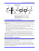
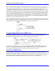
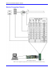

Table Of Contents
- Base Version
- Option 2: Dual-Ported RAM
- Option 5xF: CPU Speed Options
- Option 6: Extended Servo Algorithm Firmware
- Option 6L: Special Lookahead Firmware
- Option 10: Firmware Version Specification
- Option 12: Analog-to-Digital Converters
- Option 15: V-to-F Converter for Analog Input
- Option 16: Battery-Backed Parameter Memory
- Digital Power Supply
- Analog Power Supply
- Resistor Pack Configuration: Flag and Digital Inputs Voltage Selection
- Types of Overtravel Limits
- Home Switches
- Incremental Encoder Connection
- DAC Output Signals
- Amplifier Enable Signal (AENAx/DIRn)
- Amplifier Fault Signal (FAULTn)
- Command Inputs
- Selector Inputs
- Alternate Use
- Reset Input
- Handwheel Inputs
- Optional Voltage to Frequency Converter
- J1 - Display Port (JDISP Port)
- J2 - Control-Panel Port (JPAN Port)
- J3 - Thumbwheel Multiplexer Port (JTHW Port)
- J4 - Serial Port (JRS422 Port)
- J5 - General-Purpose Digital Inputs and Outputs (JOPTO Port)
- J6 – Expansion Port \(JXIO Port\)
- J8 - Machine Connectors (JMACH Port)
- J9 – Compare Equal Outputs Port \(JEQU Port\)
- J17 - Serial Port (JRS232 Port)
- J30 – Optional Analog to Digital Inputs \(JANA P
- J31 – Optional Universal Serial Bus Port \(JUSB
- JS1 – Expansion Ports \(JS1 Port\)
- TB1 – Power Supply Terminal Block \(JPWR Connect
- LED Indicators
- Fuse
- J1 (JDISP)/Display
- J2 (JPAN)/Control Panel
- J3 (JTHW)/Multiplexer Port
- J4 (JRS422)/RS232 OR 422/Serial Communications
- J5 (JOPT)/OPTO I/O
- J6 (JXIO)/Expansion Board
- J8 (JMACH)/Machine Connector
- JS1/A-D Inputs 1-4
- JEQU/Position Compare
- JANA/Analog Inputs Option
PMAC PCI-Lite Hardware Reference Manual
14 Machine Connections
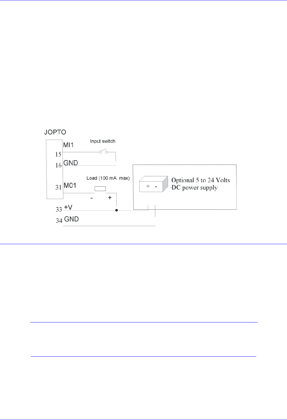
PMAC is shipped standard with a ULN2803A sinking (open-collector) output IC for the eight outputs.
These outputs can sink up to 100mA and have an internal 3.3 kΩ pull-up resistor to go high (RP18). A
high-side voltage (+5 to +24V) may be provided to pin 33 of the JOPTO connector, and allow this to pull
up the outputs by connecting pins 1 and 2 of jumper E1. In addition, jumper E2 must connect pins 1 and
2 for a ULN2803A sinking output.
It is possible for these outputs to be sourcing drivers by substituting a UDN2981A IC for the ULN2803A.
This U13 IC is socketed, and so may be replaced easily. For this driver, the internal resistor packs pull-
down instead. With a UDN2981A driver IC, Jumper E1 must connect pins 2 and 3, and Jumper E2 must
connect pins 2 and 3.
The outputs can be configured individually to a different output voltage by removing the internal pull-up
resistor pack RP18 and connecting a separate external pull-up resistor to the desired voltage level to each
output.
Example: Standard configuration using the ULN2803A sinking (open-collector) output IC
Control-Panel Port I/O (JPAN Port)
The J2 (JPAN) connector is a 26-pin connector with dedicated control inputs, dedicated indicator outputs,
a quadrature encoder input, and an analog input. The control inputs are low-true with internal pull-up
resistors. They have predefined functions unless the control-panel-disable I-variable (I2) has been set to
1. If this is the case, they may be used as general-purpose inputs by assigning M-variable to their
corresponding memory-map locations (bits of Y address $FFC0).
Command Inputs
JOG-/, JOG+/, PREJ/ (return to pre-jog position), and HOME/ affect the motor selected by the FDPn/
lines (see below). The ones that affect a coordinate system are STRT/ (run), STEP/, STOP/ (abort), and
HOLD/ (feed hold) affect the coordinate system selected by the FDPn/ lines.
Caution:
It is not a good idea to change the selector inputs while holding one of the jog
inputs low, for releasing the jog input will not stop the previously selected motor.
This can lead to a dangerous situation.