
Reference Manual
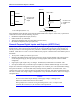

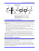
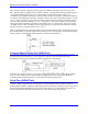
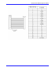
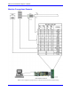

Table Of Contents
- Base Version
- Option 2: Dual-Ported RAM
- Option 5xF: CPU Speed Options
- Option 6: Extended Servo Algorithm Firmware
- Option 6L: Special Lookahead Firmware
- Option 10: Firmware Version Specification
- Option 12: Analog-to-Digital Converters
- Option 15: V-to-F Converter for Analog Input
- Option 16: Battery-Backed Parameter Memory
- Digital Power Supply
- Analog Power Supply
- Resistor Pack Configuration: Flag and Digital Inputs Voltage Selection
- Types of Overtravel Limits
- Home Switches
- Incremental Encoder Connection
- DAC Output Signals
- Amplifier Enable Signal (AENAx/DIRn)
- Amplifier Fault Signal (FAULTn)
- Command Inputs
- Selector Inputs
- Alternate Use
- Reset Input
- Handwheel Inputs
- Optional Voltage to Frequency Converter
- J1 - Display Port (JDISP Port)
- J2 - Control-Panel Port (JPAN Port)
- J3 - Thumbwheel Multiplexer Port (JTHW Port)
- J4 - Serial Port (JRS422 Port)
- J5 - General-Purpose Digital Inputs and Outputs (JOPTO Port)
- J6 – Expansion Port \(JXIO Port\)
- J8 - Machine Connectors (JMACH Port)
- J9 – Compare Equal Outputs Port \(JEQU Port\)
- J17 - Serial Port (JRS232 Port)
- J30 – Optional Analog to Digital Inputs \(JANA P
- J31 – Optional Universal Serial Bus Port \(JUSB
- JS1 – Expansion Ports \(JS1 Port\)
- TB1 – Power Supply Terminal Block \(JPWR Connect
- LED Indicators
- Fuse
- J1 (JDISP)/Display
- J2 (JPAN)/Control Panel
- J3 (JTHW)/Multiplexer Port
- J4 (JRS422)/RS232 OR 422/Serial Communications
- J5 (JOPT)/OPTO I/O
- J6 (JXIO)/Expansion Board
- J8 (JMACH)/Machine Connector
- JS1/A-D Inputs 1-4
- JEQU/Position Compare
- JANA/Analog Inputs Option

PMAC PCI Lite Hardware Reference Manual
Machine Connections 13
49
FAULT1
AGND
58
Connect to the
amplifier fault
output
JMACH1
49
FAULT1
JEQU, PIN 9
Connect to the
amplifier fault
output
+
-
12-15 Volts signal (E100 on 1-2)
15-24 Volts signal (E100 on 2-3)
12-23V
DC
Some amplifiers share the fault output with the enable/disable status output. In this case, a special PLC
code must be written with the following sequence:
• Disable the amplifier fault input (see Ix25)
• Enable the motor (J/ command).
• Wait for the amplifier fault input to be false (monitor Mx23).
• Re-enable the amplifier fault input (see Ix25).
General-Purpose Digital Inputs and Outputs (JOPTO Port)
PMAC’s J5 or JOPTO connector provides eight general-purpose digital inputs and eight general-purpose
digital outputs. Each input and each output has its own corresponding ground pin in the opposite row.
The 34-pin connector was designed for easy interface to OPTO-22 or equivalent optically isolated I/O
modules. Delta Tau’s Acc-21F is a six-foot cable for this purpose. Characteristics of the JOPTO port on
the PMAC:
• 16 I/O points. 100mA per channel, up to 24V
• Hardware selectable between sinking and sourcing in groups of eight; default is all sinking (inputs
can be changed simply by moving a jumper; sourcing outputs must be special-ordered or field-
configured)
• Eight inputs, eight outputs only; no changes. Parallel (fast) communications to PMAC CPU
• Not opto-isolated; easily connected to Opto-22 (PB16) or similar modules through Acc-21F cable
Jumper E7 controls the configuration of the eight inputs. If it connects pins 1 and 2 (the default setting),
the inputs are biased to +5V for the OFF state, and they must be pulled low for the ON state. If E7
connects pins 2 and 3, the inputs are biased to ground for the OFF state, and must be pulled high for the
ON state. In either case, a high voltage is interpreted as a 0 by the PMAC software, and a low voltage is
interpreted as a 1.
Caution:
Do not connect these outputs directly to the supply voltage, or damage to the
PMAC will result from excessive current draw.
Having Jumpers E1 and E2 set wrong can damage the IC. The +V output on this
connector has a 2A fuse, F1, for excessive current protection.