
Reference Manual
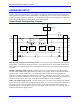
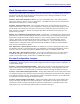
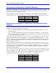

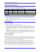
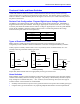
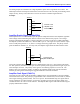
Table Of Contents
- Base Version
- Option 2: Dual-Ported RAM
- Option 5xF: CPU Speed Options
- Option 6: Extended Servo Algorithm Firmware
- Option 6L: Special Lookahead Firmware
- Option 10: Firmware Version Specification
- Option 12: Analog-to-Digital Converters
- Option 15: V-to-F Converter for Analog Input
- Option 16: Battery-Backed Parameter Memory
- Digital Power Supply
- Analog Power Supply
- Resistor Pack Configuration: Flag and Digital Inputs Voltage Selection
- Types of Overtravel Limits
- Home Switches
- Incremental Encoder Connection
- DAC Output Signals
- Amplifier Enable Signal (AENAx/DIRn)
- Amplifier Fault Signal (FAULTn)
- Command Inputs
- Selector Inputs
- Alternate Use
- Reset Input
- Handwheel Inputs
- Optional Voltage to Frequency Converter
- J1 - Display Port (JDISP Port)
- J2 - Control-Panel Port (JPAN Port)
- J3 - Thumbwheel Multiplexer Port (JTHW Port)
- J4 - Serial Port (JRS422 Port)
- J5 - General-Purpose Digital Inputs and Outputs (JOPTO Port)
- J6 – Expansion Port \(JXIO Port\)
- J8 - Machine Connectors (JMACH Port)
- J9 – Compare Equal Outputs Port \(JEQU Port\)
- J17 - Serial Port (JRS232 Port)
- J30 – Optional Analog to Digital Inputs \(JANA P
- J31 – Optional Universal Serial Bus Port \(JUSB
- JS1 – Expansion Ports \(JS1 Port\)
- TB1 – Power Supply Terminal Block \(JPWR Connect
- LED Indicators
- Fuse
- J1 (JDISP)/Display
- J2 (JPAN)/Control Panel
- J3 (JTHW)/Multiplexer Port
- J4 (JRS422)/RS232 OR 422/Serial Communications
- J5 (JOPT)/OPTO I/O
- J6 (JXIO)/Expansion Board
- J8 (JMACH)/Machine Connector
- JS1/A-D Inputs 1-4
- JEQU/Position Compare
- JANA/Analog Inputs Option

PMAC PCI-Lite Hardware Reference Manual
12 Machine Connections
The analog outputs are intended to drive high-impedance inputs with no significant current draw. The
220Ω output resistors will keep the current draw lower than 50 mA in all cases and prevent damage to the
output circuitry, but any current draw above 10 mA can result in noticeable signal distortion.
Example:
JMACH1
DAC1
DAC1/
AGND
43
45
58
Connect to the
amplifier +10V
command input
Amplifier Enable Signal (AENAx/DIRn)
Most amplifiers have an enable/disable input that permits complete shutdown of the amplifier regardless
of the voltage of the command signal. PMAC’s AENA line is meant for this purpose. If not using a
direction and magnitude amplifier or voltage-to-frequency converter, use this pin to enable and disable
the amplifier (wired to the enable line). AENA1/DIR1 is pin 47. This signal is an open-collector output
with a 3.3 kΩ pull-up resistor to +V, which is a voltage selected by jumper E100. The pull-up resistor
packs are RP43 for channels 1-4. For early tests, this amplifier signal should be under manual control.
JMACH1
AENA1
AGND
47
58
Connect to the
amplifier enable input
This signal could be either sinking or sourcing as determined by chips U37. (See jumpers E100-E102.)
For 24V operation, E100 must connect pins 2-3 and a separate power supply must be brought on pins 9-7
of the J9 JEQU connector. The polarity of the signal is controlled by jumpers E17A to E17D. The
default is low-true (conducting) enable. In addition, the amplifier enable signal could be controlled
manually by setting Ix00=0 and using the suggested definition of the Mx14 variable.
Amplifier Fault Signal (FAULTn)
This input can take a signal from the amplifier so PMAC knows when the amplifier is having problems,
and can shut down action. The polarity is programmable with I-variable Ix25 (I125 for motor #1) and the
return signal is analog ground (AGND). FAULT1 is pin 49. With the default setup, this signal must be
actively pulled low for a fault condition. In this setup, if nothing is wired into this input, PMAC will
consider the motor not to be in a fault condition. The amplifier fault signal could be monitored using the
properly defined Mx23 variable.