
Reference Manual

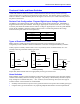
Table Of Contents
- Base Version
- Option 2: Dual-Ported RAM
- Option 5xF: CPU Speed Options
- Option 6: Extended Servo Algorithm Firmware
- Option 6L: Special Lookahead Firmware
- Option 10: Firmware Version Specification
- Option 12: Analog-to-Digital Converters
- Option 15: V-to-F Converter for Analog Input
- Option 16: Battery-Backed Parameter Memory
- Digital Power Supply
- Analog Power Supply
- Resistor Pack Configuration: Flag and Digital Inputs Voltage Selection
- Types of Overtravel Limits
- Home Switches
- Incremental Encoder Connection
- DAC Output Signals
- Amplifier Enable Signal (AENAx/DIRn)
- Amplifier Fault Signal (FAULTn)
- Command Inputs
- Selector Inputs
- Alternate Use
- Reset Input
- Handwheel Inputs
- Optional Voltage to Frequency Converter
- J1 - Display Port (JDISP Port)
- J2 - Control-Panel Port (JPAN Port)
- J3 - Thumbwheel Multiplexer Port (JTHW Port)
- J4 - Serial Port (JRS422 Port)
- J5 - General-Purpose Digital Inputs and Outputs (JOPTO Port)
- J6 – Expansion Port \(JXIO Port\)
- J8 - Machine Connectors (JMACH Port)
- J9 – Compare Equal Outputs Port \(JEQU Port\)
- J17 - Serial Port (JRS232 Port)
- J30 – Optional Analog to Digital Inputs \(JANA P
- J31 – Optional Universal Serial Bus Port \(JUSB
- JS1 – Expansion Ports \(JS1 Port\)
- TB1 – Power Supply Terminal Block \(JPWR Connect
- LED Indicators
- Fuse
- J1 (JDISP)/Display
- J2 (JPAN)/Control Panel
- J3 (JTHW)/Multiplexer Port
- J4 (JRS422)/RS232 OR 422/Serial Communications
- J5 (JOPT)/OPTO I/O
- J6 (JXIO)/Expansion Board
- J8 (JMACH)/Machine Connector
- JS1/A-D Inputs 1-4
- JEQU/Position Compare
- JANA/Analog Inputs Option
PMAC PCI Lite Hardware Reference Manual
Machine Connections 11
Motor Signals Connections (JMACH Connectors)
Incremental Encoder Connection
Each JMACH connector provides two +5V outputs and two logic grounds for powering encoders and
other devices. The +5V outputs are on pins 1 and 2; the grounds are on pins 3 and 4. The encoder signal
pins are grouped by number: all those numbered 1 (CHA1, CHA1/, CHB1, CHC1, etc.) belong to encoder
#1. Usually, the encoder number matches the motor number, but it is not necessary. If the PMAC is not
plugged into a bus and drawing its +5V and GND from the bus, use these pins to bring in +5V and GND
from the power supply. Connect the A and B (quadrature) encoder channels to the appropriate terminal
block pins. For encoder 1, the CHA1 is pin 25, CHB1 is pin 21. If there is a single-ended signal, leave
the complementary signal pins floating — do not ground them. However, if single-ended encoders are
used, make sure the resistor packs are in the default position (RP-60/62/66/68). For a differential
encoder, connect the complementary signal lines — CHA1/ is pin 27, and CHB1/ is pin 23. The third
channel (index pulse) is optional; for encoder 1, CHC1 is pin 17, and CHC1/ is pin 19.
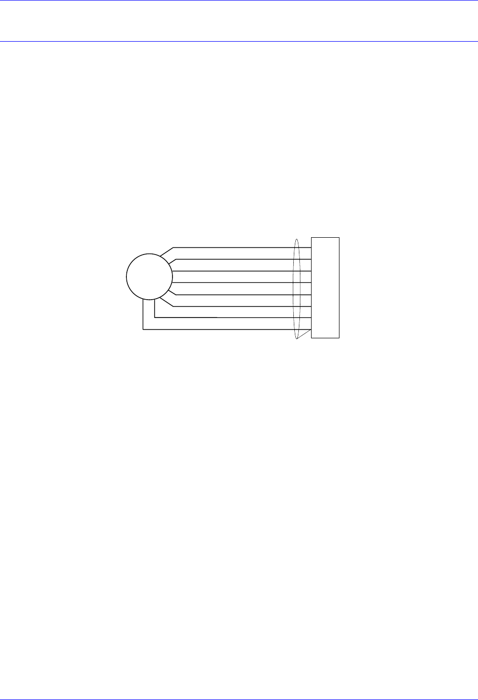
Example: differential quadrature encoder connected to channel #1:
JMACH
17
19
21
23
25
27
1
3
A
B
C
5V
DAC Output Signals
If PMAC is not performing the commutation for the motor, only one analog output channel is required to
command the motor. This output channel can be either single-ended or differential, depending on what
the amplifier is expecting. For a single-ended command using PMAC channel 1, connect DAC1 (pin 43)
to the command input on the amplifier. Connect the amplifier's command signal return line to PMAC's
AGND line (pin 58). In this setup, leave the DAC1/ pin floating. Do not ground it.
For a differential command using PMAC channel 1, connect DAC1 (pin 43) to the plus-command input
on the amplifier. Connect DAC1/ (pin 45) to the minus-command input on the amplifier. PMAC’s
AGND should still be connected to the amplifier common. If the amplifier is expecting separate sign and
magnitude signals, connect DAC1 (pin 43) to the magnitude input. Connect AENA1/DIR1 (pin 47) to the
sign (direction input). Amplifier signal returns should be connected to AGND (pin 58). This format
requires some parameter changes on PMAC. (See Ix02 and Ix25.) Jumper E17 controls the polarity of
the direction output. This may have to be changed during the polarity test. This magnitude-and-direction
mode is suited for driving servo amplifiers that expect this type of input, and for driving voltage-to-
frequency (V/F) converters, such as PMAC’s Acc-8D Option 2 board, for running stepper motor drivers.
If using PMAC to commutate the motor, use two analog output channels for the motor. Each output may
be single-ended or differential, just as for the DC motor. The two channels must be consecutively
numbered, with the lower-numbered channel having an odd number (e.g., use DAC1 and DAC2 for a
motor, or DAC3 and DAC4, but not DAC2 and DAC3, or DAC2 and DAC4). For our motor #1 example,
connect DAC1 (pin 43) and DAC2 (pin 45) to the analog inputs of the amplifier. If using the
complements as well, connect DAC1/ (pin 45) and DAC2/ (pin 46) the minus-command inputs; otherwise
leave the complementary signal outputs floating. To limit the range of each signal to +/- 5V, use
parameter Ix69. Any analog output not used for dedicated servo purposes may be utilized as a general-
purpose analog output. Usually this is done by defining an M-variable to the digital-to-analog-converter
register (suggested M-variable definitions M102, M202, etc.), then writing values to the M-variable.