
Reference Manual
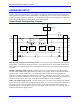
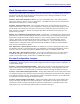
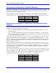

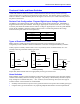
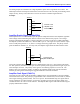
Table Of Contents
- Base Version
- Option 2: Dual-Ported RAM
- Option 5xF: CPU Speed Options
- Option 6: Extended Servo Algorithm Firmware
- Option 6L: Special Lookahead Firmware
- Option 10: Firmware Version Specification
- Option 12: Analog-to-Digital Converters
- Option 15: V-to-F Converter for Analog Input
- Option 16: Battery-Backed Parameter Memory
- Digital Power Supply
- Analog Power Supply
- Resistor Pack Configuration: Flag and Digital Inputs Voltage Selection
- Types of Overtravel Limits
- Home Switches
- Incremental Encoder Connection
- DAC Output Signals
- Amplifier Enable Signal (AENAx/DIRn)
- Amplifier Fault Signal (FAULTn)
- Command Inputs
- Selector Inputs
- Alternate Use
- Reset Input
- Handwheel Inputs
- Optional Voltage to Frequency Converter
- J1 - Display Port (JDISP Port)
- J2 - Control-Panel Port (JPAN Port)
- J3 - Thumbwheel Multiplexer Port (JTHW Port)
- J4 - Serial Port (JRS422 Port)
- J5 - General-Purpose Digital Inputs and Outputs (JOPTO Port)
- J6 – Expansion Port \(JXIO Port\)
- J8 - Machine Connectors (JMACH Port)
- J9 – Compare Equal Outputs Port \(JEQU Port\)
- J17 - Serial Port (JRS232 Port)
- J30 – Optional Analog to Digital Inputs \(JANA P
- J31 – Optional Universal Serial Bus Port \(JUSB
- JS1 – Expansion Ports \(JS1 Port\)
- TB1 – Power Supply Terminal Block \(JPWR Connect
- LED Indicators
- Fuse
- J1 (JDISP)/Display
- J2 (JPAN)/Control Panel
- J3 (JTHW)/Multiplexer Port
- J4 (JRS422)/RS232 OR 422/Serial Communications
- J5 (JOPT)/OPTO I/O
- J6 (JXIO)/Expansion Board
- J8 (JMACH)/Machine Connector
- JS1/A-D Inputs 1-4
- JEQU/Position Compare
- JANA/Analog Inputs Option
PMAC PCI-Lite Hardware Reference Manual
10 Machine Connections
Overtravel Limits and Home Switches
When assigned for the dedicated uses, these signals provide important safety and accuracy functions.
+LIMn and -LIMn are direction-sensitive overtravel limits that must be actively held low (sourcing
current from the pins to ground) to permit motion in their direction. The direction sense of +LIMn and -
LIMn is as follows: +LIMn should be placed at the negative end of travel, and -LIMn should be placed at
the positive end of travel.
Resistor Pack Configuration: Flag and Digital Inputs Voltage Selection
The PMAC is provided with 6-pin sockets for SIP resistor packs for the input flag sets. Each PMAC is
shipped without resistor packs installed. If the flag or digital inputs circuits are in the 12V to 15V range,
no resistor pack should be installed in these sockets. For flags or digital inputs at 5V levels, quad 1kΩ SIP
resistor packs (1KSIP6C) should be installed in these sockets. The following table lists the voltage
selection resistor pack sockets for each input device:
Device Resistor Pack
Flags 1 RP77
Flags 2 RP83
Flags 3 RP89
Flags 4 RP94
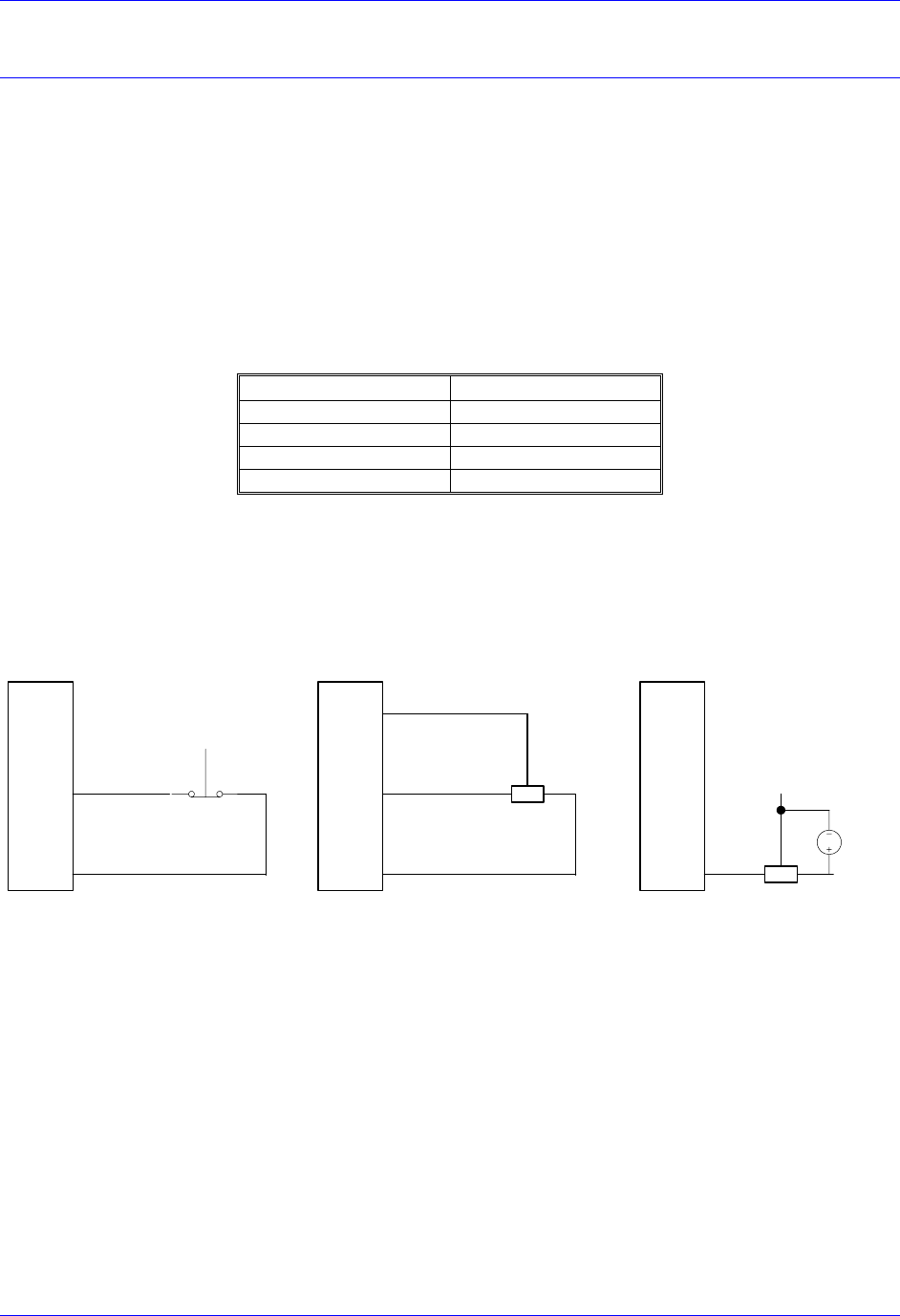
Types of Overtravel Limits
PMAC expects a closed-to-ground connection for the limits to be considered not on fault. This
arrangement provides a failsafe condition and therefore it cannot be reconfigured differently in PMAC.
Usually a passive normally closed switch is used. If a proximity switch is needed instead, use a 15V
normally closed to ground NPN sinking type sensor.
JMACH1
+Lim
AGnd
51
58
Dry Contact
51
59
58
+Lim
AGnd
+15V
Output
JMACH
+Lim
51
JMACH1
DC
12-24V
JMACH2, PIN 59
+-
15 Volts proximity 15-24 Volts proximity
Jumper E89, E90 and E100 must be set appropriately for the type of sensor used.
Home Switches
While normally closed-to-ground switches are required for the overtravel limits inputs, the home switches
could be either normally closed or normally open types. The polarity is determined by the home sequence
setup, through the I-variables I902, I907, ... I977. However, for the following reasons, the same type of
switches used for overtravel limits are recommended:
• Normally closed switches are proven to have greater electrical noise rejection than normally open types.
• Using the same type of switches for every input flag simplifies maintenance stock and replacements.