
Reference Manual
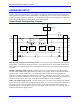
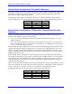

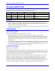
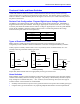
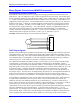
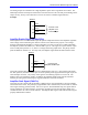
Table Of Contents
- Base Version
- Option 2: Dual-Ported RAM
- Option 5xF: CPU Speed Options
- Option 6: Extended Servo Algorithm Firmware
- Option 6L: Special Lookahead Firmware
- Option 10: Firmware Version Specification
- Option 12: Analog-to-Digital Converters
- Option 15: V-to-F Converter for Analog Input
- Option 16: Battery-Backed Parameter Memory
- Digital Power Supply
- Analog Power Supply
- Resistor Pack Configuration: Flag and Digital Inputs Voltage Selection
- Types of Overtravel Limits
- Home Switches
- Incremental Encoder Connection
- DAC Output Signals
- Amplifier Enable Signal (AENAx/DIRn)
- Amplifier Fault Signal (FAULTn)
- Command Inputs
- Selector Inputs
- Alternate Use
- Reset Input
- Handwheel Inputs
- Optional Voltage to Frequency Converter
- J1 - Display Port (JDISP Port)
- J2 - Control-Panel Port (JPAN Port)
- J3 - Thumbwheel Multiplexer Port (JTHW Port)
- J4 - Serial Port (JRS422 Port)
- J5 - General-Purpose Digital Inputs and Outputs (JOPTO Port)
- J6 – Expansion Port \(JXIO Port\)
- J8 - Machine Connectors (JMACH Port)
- J9 – Compare Equal Outputs Port \(JEQU Port\)
- J17 - Serial Port (JRS232 Port)
- J30 – Optional Analog to Digital Inputs \(JANA P
- J31 – Optional Universal Serial Bus Port \(JUSB
- JS1 – Expansion Ports \(JS1 Port\)
- TB1 – Power Supply Terminal Block \(JPWR Connect
- LED Indicators
- Fuse
- J1 (JDISP)/Display
- J2 (JPAN)/Control Panel
- J3 (JTHW)/Multiplexer Port
- J4 (JRS422)/RS232 OR 422/Serial Communications
- J5 (JOPT)/OPTO I/O
- J6 (JXIO)/Expansion Board
- J8 (JMACH)/Machine Connector
- JS1/A-D Inputs 1-4
- JEQU/Position Compare
- JANA/Analog Inputs Option

PMAC PCI Lite Hardware Reference Manual
Machine Connections 9
MACHINE CONNECTIONS
Typically, the user connections are made to a terminal block that is attached to the JMACH connector by
a flat cable (Accessory 8D or 8P). The pin-out numbers on the terminal block are the same as those on
the JMACH connector. The possible choices for breakout boards are:
Board Mounting Breakout Style Breakout Connector Notes
Acc-8P DIN – Rail Monolithic Terminal Block Simple Phoenix contact board
Acc-8D DIN – Rail Monolithic Terminal Block
Headers for connection to option
boards
Acc-8DCE DIN – Rail Modular D-sub connector
Fully shielded for easy CE mark
compliance
Mounting
The PMAC can be mounted in one of two ways: in the PCI bus, or using standoffs.
• PCI bus: To mount in the PCI bus, simply insert the P1 card-edge connector into the PCI socket. If
there is a standard PC-style housing, a bracket at the end of the PMAC board can be used to screw
into the housing to hold the board down firmly.
• Standoffs: At each of the four corners of the PMAC board, there are mounting holes that can be used
to mount the board on standoffs.
Power Supplies
Digital Power Supply
2A @ +5V (+/-5%) (10W)
(Eight-channel configuration with a typical load of encoders)
• The host computer provides the 5V-power supply if PMAC is installed in its internal bus.
With the board plugged into the bus, it will pull +5V power from the bus automatically and it cannot
be disconnected. In this case, there must be no external +5V supply, or the two supplies will fight
each other, possibly causing damage. This voltage could be measured between pins 1 and 3 of the
terminal block.
• In a stand-alone configuration, when PMAC is not plugged in a computer bus, it will need an external
5V supply to power its digital circuits. The +5V line from the supply should be connected to pin 1 or
2 of the JMACH connector (usually through the terminal block), and the digital ground to pin 3 or 4.
Acc-1x provides different options for the 5V-power supply.
Analog Power Supply
0.3A @ +12 to +15V (4.5W)
0.25A @ -12 to -15V (3.8W)
The analog output circuitry on PMAC is optically isolated from the digital computation circuitry, and so
requires a separate power supply. Bring this in on the JMACH connector. Bring the positive supply (+12
to +15V) in on the A+15V line on pin 59. Bring the negative supply (-12 to -15V) in on the A-15V line
on pin 60 and the analog common in on the AGND line on pin 58.
Typically, this supply can come from the servo amplifier; many commercial amplifiers provide such a
supply, or an external supply may be used. Acc-2x provides different options for the ± 15V power
supply. Even with an external supply, the AGND line should be tied to the amplifier common. It is
possible to get the power for the analog circuits from the bus, but doing so defeats optical isolation. In
this case, no new connections need to be made. However, be sure jumpers E85, E87, E88, E89, and E90
are set up for this circumstance. (The card is not shipped from the factory in this configuration.)