
Reference Manual

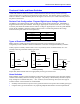
Table Of Contents
- Base Version
- Option 2: Dual-Ported RAM
- Option 5xF: CPU Speed Options
- Option 6: Extended Servo Algorithm Firmware
- Option 6L: Special Lookahead Firmware
- Option 10: Firmware Version Specification
- Option 12: Analog-to-Digital Converters
- Option 15: V-to-F Converter for Analog Input
- Option 16: Battery-Backed Parameter Memory
- Digital Power Supply
- Analog Power Supply
- Resistor Pack Configuration: Flag and Digital Inputs Voltage Selection
- Types of Overtravel Limits
- Home Switches
- Incremental Encoder Connection
- DAC Output Signals
- Amplifier Enable Signal (AENAx/DIRn)
- Amplifier Fault Signal (FAULTn)
- Command Inputs
- Selector Inputs
- Alternate Use
- Reset Input
- Handwheel Inputs
- Optional Voltage to Frequency Converter
- J1 - Display Port (JDISP Port)
- J2 - Control-Panel Port (JPAN Port)
- J3 - Thumbwheel Multiplexer Port (JTHW Port)
- J4 - Serial Port (JRS422 Port)
- J5 - General-Purpose Digital Inputs and Outputs (JOPTO Port)
- J6 – Expansion Port \(JXIO Port\)
- J8 - Machine Connectors (JMACH Port)
- J9 – Compare Equal Outputs Port \(JEQU Port\)
- J17 - Serial Port (JRS232 Port)
- J30 – Optional Analog to Digital Inputs \(JANA P
- J31 – Optional Universal Serial Bus Port \(JUSB
- JS1 – Expansion Ports \(JS1 Port\)
- TB1 – Power Supply Terminal Block \(JPWR Connect
- LED Indicators
- Fuse
- J1 (JDISP)/Display
- J2 (JPAN)/Control Panel
- J3 (JTHW)/Multiplexer Port
- J4 (JRS422)/RS232 OR 422/Serial Communications
- J5 (JOPT)/OPTO I/O
- J6 (JXIO)/Expansion Board
- J8 (JMACH)/Machine Connector
- JS1/A-D Inputs 1-4
- JEQU/Position Compare
- JANA/Analog Inputs Option

PMAC PCI Lite Hardware Reference Manual
Hardware Setup 5
Board Reset/Save Jumpers
E50: Flash-Save Enable/Disable Control – If E50 is ON (default), the active software configuration of
the PMAC can be stored to non-volatile flash memory with the SAVE command. If the jumper on E50 is
removed, this SAVE function is disabled, and the contents of the flash memory cannot be changed.
E51: Re-Initialization on Reset Control – If E51 is OFF (default), PMAC executes a normal reset,
loading active memory from the last saved configuration in non-volatile flash memory. If E51 is ON,
PMAC re-initializes on reset, loading active memory with the factory default values.
Communication Jumpers
PCI Bus Base Address Control – The selection of the base address of the card in the I/O space of the
host PC’s expansion bus is assigned automatically by the operating system and is not selected through a
jumper configuration as ISA bus address would be.
E44-E47: Serial Baud Rate Selection – If the saved value of I46 is 0, the CPU’s operational frequency
is determined by the E48 jumper settings. Then the serial baud rate is determined by a combination of the
setting of jumpers E44-E47 and the CPU frequency on a PMAC(1) board. If the CPU’s operational
frequency has been determined by a non-zero setting of I46, the serial communications baud rate is
determined only by variable I54 at power-up/reset. See the Software Setup section of this manual for
details.
E49: Serial Communications Parity Control – Jump pin 1 to 2 for NO serial parity; remove jumper for
ODD serial parity.
E54-E65: Interrupt Source Control – These jumpers control which signals are tied to interrupt lines
IR5, IR6 and IR7 on PMAC’s programmable interrupt controller (PIC) as shown in the interrupt diagram.
Only one signal may be tied into each of these lines.
E110: Serial Port Configure – Jump pin 1 to 2 for use of the J4 connector as RS232. Jump pin 2 to 3
for use of the J4 connector as RS422. This jumper must be set the same as E111 (only RS-422 can output
phase and servo).
E111: Clock Lines Output Enable – Jump pin 2 to 3 to enable the Phase, Servo and Init lines on the J4
connector. Jump pin 2 to 3 to disable the Phase, Servo and Init lines on the J4 connector. For daisy
chained PMACs sharing the clock lines for synchronization, E111 must be on positions 1 to 2. This
jumper must be set the same as E110 (only RS-422 can output phase and servo).
I/O Configuration Jumpers
E1-E2: Machine Output Supply Configure – With the default sinking output driver IC (ULN2803A or
equivalent) in U13 for the J5 JOPTO port outputs, these jumpers must connect pins 1 and 2 to supply the
IC correctly. If this IC is replaced with a sourcing output driver IC (UDN2981A or equivalent), these
jumpers must be changed to connect pins 2 and 3 to supply the new IC correctly.
Caution:
A wrong setting of these jumpers will damage the associated output IC.
E7: Machine Input Source/Sink Control – With this jumper connecting pins 1 and 2 (default) the
machine input lines on the J5 JOPTO port are pulled up to +5V or the externally provided supply voltage
for the port. This configuration is suitable for sinking drivers. If the jumper is changed to connect pins 2
and 3, these lines are pulled down to GND – this configuration is suitable for sourcing drivers.