
Reference Manual
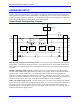

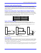
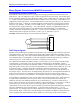
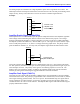
Table Of Contents
- Base Version
- Option 2: Dual-Ported RAM
- Option 5xF: CPU Speed Options
- Option 6: Extended Servo Algorithm Firmware
- Option 6L: Special Lookahead Firmware
- Option 10: Firmware Version Specification
- Option 12: Analog-to-Digital Converters
- Option 15: V-to-F Converter for Analog Input
- Option 16: Battery-Backed Parameter Memory
- Digital Power Supply
- Analog Power Supply
- Resistor Pack Configuration: Flag and Digital Inputs Voltage Selection
- Types of Overtravel Limits
- Home Switches
- Incremental Encoder Connection
- DAC Output Signals
- Amplifier Enable Signal (AENAx/DIRn)
- Amplifier Fault Signal (FAULTn)
- Command Inputs
- Selector Inputs
- Alternate Use
- Reset Input
- Handwheel Inputs
- Optional Voltage to Frequency Converter
- J1 - Display Port (JDISP Port)
- J2 - Control-Panel Port (JPAN Port)
- J3 - Thumbwheel Multiplexer Port (JTHW Port)
- J4 - Serial Port (JRS422 Port)
- J5 - General-Purpose Digital Inputs and Outputs (JOPTO Port)
- J6 – Expansion Port \(JXIO Port\)
- J8 - Machine Connectors (JMACH Port)
- J9 – Compare Equal Outputs Port \(JEQU Port\)
- J17 - Serial Port (JRS232 Port)
- J30 – Optional Analog to Digital Inputs \(JANA P
- J31 – Optional Universal Serial Bus Port \(JUSB
- JS1 – Expansion Ports \(JS1 Port\)
- TB1 – Power Supply Terminal Block \(JPWR Connect
- LED Indicators
- Fuse
- J1 (JDISP)/Display
- J2 (JPAN)/Control Panel
- J3 (JTHW)/Multiplexer Port
- J4 (JRS422)/RS232 OR 422/Serial Communications
- J5 (JOPT)/OPTO I/O
- J6 (JXIO)/Expansion Board
- J8 (JMACH)/Machine Connector
- JS1/A-D Inputs 1-4
- JEQU/Position Compare
- JANA/Analog Inputs Option
PMAC PCI Lite Hardware Reference Manual
Hardware Setup 3
HARDWARE SETUP
On the PMAC, there are many jumpers (pairs of metal prongs), called E-points. Some have been shorted
together; others have been left open. These jumpers customize the hardware features of the board for a
given application and must be set up appropriately. The following is an overview of the several PMAC
jumpers grouped in appropriate categories. For a complete description of the jumper setup configuration,
refer to the CPU Board E-Point Descriptions section of this manual.
Power-Supply Configuration Jumpers
(12-24V) A+V (pin 9)
J9 (JEQU)
Input
Flags
AENAs
(EQUs)
V/F DACs
+12V
+5V
-12V
GND
P1 (Bus) / TB1
E90
E85
E100
E89
3
1
1
3
E87
E88
JMACH1
A+15V
+5V
AGND
GND
A-15V
AGND
E85, E87, E88: Analog Circuit Isolation Control – These jumpers control whether the analog circuitry
on the PMAC is isolated from the digital circuitry, or electrically tied to it. In the default configuration,
these jumpers are off, keeping the circuits isolated from each other (provided separate isolated supplies
are used).
E89-E90: Input Flag Supply Control – If E90 connects pins 1 and 2 and E89 is ON, the input flags
(+LIMn, -LIMn, HMFLn) are supplied from the analog A+15V supply, which can be isolated from the
digital circuitry. If E90 connects pins 1 and 2 and E89 is OFF, the input flags are supplied from a
separate A+V supply through pin 9 of the J9 JEQU connector. This supply can be in the +12V to +24V
range, and can be kept isolated from the digital circuitry. If E90 connects pins 2 and 3, the input flags are
supplied from the digital +12V supply, and isolation from the digital circuitry is defeated.
E100: AENA/EQU Supply Control – If E100 connects pins 1 and 2, the circuits related to the AENAn,
EQUn and FAULTn signals will be supplied from the analog A+15V supply, which can be isolated from
the digital circuitry. If E100 connects pins 2 and 3, the circuits will be supplied from a separate A+V
supply through pin 9 of the J9 JEQU connector. This supply can be in the +12V to +24V range, and can
be kept isolated from the digital circuitry.