^1 HARDWARE REFERENCE MANUAL ^2 PMAC PCI Lite ^3 PCI Format 4-Axis Control Board ^4 400-603657-xHxx ^5 August 14, 2007 Single Source Machine Control Power // Flexibility // Ease of Use 21314 Lassen Street Chatsworth, CA 91311 // Tel. (818) 998-2095 Fax. (818) 998-7807 // www.deltatau.
Copyright Information © 2007 Delta Tau Data Systems, Inc. All rights reserved. This document is furnished for the customers of Delta Tau Data Systems, Inc. Other uses are unauthorized without written permission of Delta Tau Data Systems, Inc. Information contained in this manual may be updated from time-to-time due to product improvements, etc., and may not conform in every respect to former issues. To report errors or inconsistencies, call or email: Delta Tau Data Systems, Inc.
REVISION HISTORY REV. DESCRIPTION DATE CHG APPVD 1 DELETED OPTIONS 2B, 7, 8A; UPDATED ALL JUMPER/CONNECTOR INFO 10/04/06 CP P. SHANTZ 2 CORRECTION TO E17A-E17D CONTROL, P. 6 11/07/06 CP S. SATTARI 3 CORRECTIONS TO E110 & E111 JUMPER DESC. 04/26/07 CP S. MILICI 4 CORRECTION TO E122: XIN FEATURE, P. 41 08/14/07 CP B.
PMAC PCI-Lite Hardware Reference Manual Table of Contents INTRODUCTION .......................................................................................................................................................1 Board Configuration..................................................................................................................................................1 Base Version ...........................................................................................................
PMAC PCI Lite Hardware Reference Manual Operational Frequency and Baud Rate Setup..........................................................................................................21 Serial Addressing Card Number..............................................................................................................................22 Option 16 Supplemental Battery-Backed Memory .................................................................................................
PMAC PCI-Lite Hardware Reference Manual E122: XIN Feature Selection ..................................................................................................................................41 MATING CONNECTORS .......................................................................................................................................43 Base Board Connectors .....................................................................................................................................
PMAC PCI Lite Hardware Reference Manual iv Table of Contents
PMAC PCI Lite Hardware Reference Manual INTRODUCTION The PMAC PCI Lite is a member of the PMAC family of boards optimized for interface to traditional servo drives with single analog inputs representing velocity or torque commands. Its software is capable of eight axes of control, although it can have only four channels of on-board axis interface circuitry. The PMAC PCI Lite is a full-sized PCI-bus expansion card.
PMAC PCI Lite Hardware Reference Manual Option 6: Extended Servo Algorithm Firmware • Option 6 provides an Extended (Pole-Placement) Servo Algorithm firmware instead of the regular servo algorithm firmware. This is required only in difficult-to-control systems (resonances, backlash, friction, disturbances, changing dynamics). Option 6L: Special Lookahead Firmware • Option 6L provides a special lookahead firmware for sophisticated acceleration and cornering profile execution.
PMAC PCI Lite Hardware Reference Manual HARDWARE SETUP On the PMAC, there are many jumpers (pairs of metal prongs), called E-points. Some have been shorted together; others have been left open. These jumpers customize the hardware features of the board for a given application and must be set up appropriately. The following is an overview of the several PMAC jumpers grouped in appropriate categories.
PMAC PCI-Lite Hardware Reference Manual Clock Configuration Jumpers E3-E6: Servo Clock Frequency Control –Jumpers E3 – E6 determine the servo-clock frequency by controlling how many times it is divided down from the phase-frequency. The default setting of E3 and E4 OFF, E5 and E6 ON divides the phase-clock frequency by four, creating a 2.25kHz servo-clock frequency. This setting is seldom changed.
PMAC PCI Lite Hardware Reference Manual Board Reset/Save Jumpers E50: Flash-Save Enable/Disable Control – If E50 is ON (default), the active software configuration of the PMAC can be stored to non-volatile flash memory with the SAVE command. If the jumper on E50 is removed, this SAVE function is disabled, and the contents of the flash memory cannot be changed.
PMAC PCI-Lite Hardware Reference Manual E17A - E17D: Motors 1-4 Amplifier-Enable Polarity Control – Jumpers E17A through E17D control the polarity of the amplifier enable signal for the corresponding motor 1 to 4. When the jumper is OFF (default), the amplifier-enable line for the corresponding motor is low true so the enable state is lowvoltage output and sinking current, and the disable state is not conducting current.
PMAC PCI Lite Hardware Reference Manual Resistor Pack Configuration: Termination Resistors The PMAC provides sockets for termination resistors on differential input pairs coming into the board. There are no resistor packs in these sockets when shipped. If these signals are brought long distances into the PMAC board and ringing at signal transitions is a problem, SIP resistor packs may be mounted in these sockets to reduce or eliminate the ringing.
PMAC PCI-Lite Hardware Reference Manual 8 Hardware Setup
PMAC PCI Lite Hardware Reference Manual MACHINE CONNECTIONS Typically, the user connections are made to a terminal block that is attached to the JMACH connector by a flat cable (Accessory 8D or 8P). The pin-out numbers on the terminal block are the same as those on the JMACH connector.
PMAC PCI-Lite Hardware Reference Manual Overtravel Limits and Home Switches When assigned for the dedicated uses, these signals provide important safety and accuracy functions. +LIMn and -LIMn are direction-sensitive overtravel limits that must be actively held low (sourcing current from the pins to ground) to permit motion in their direction. The direction sense of +LIMn and LIMn is as follows: +LIMn should be placed at the negative end of travel, and -LIMn should be placed at the positive end of travel.
PMAC PCI Lite Hardware Reference Manual Motor Signals Connections (JMACH Connectors) Incremental Encoder Connection Each JMACH connector provides two +5V outputs and two logic grounds for powering encoders and other devices. The +5V outputs are on pins 1 and 2; the grounds are on pins 3 and 4. The encoder signal pins are grouped by number: all those numbered 1 (CHA1, CHA1/, CHB1, CHC1, etc.) belong to encoder #1. Usually, the encoder number matches the motor number, but it is not necessary.
PMAC PCI-Lite Hardware Reference Manual The analog outputs are intended to drive high-impedance inputs with no significant current draw. The 220Ω output resistors will keep the current draw lower than 50 mA in all cases and prevent damage to the output circuitry, but any current draw above 10 mA can result in noticeable signal distortion.
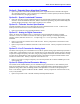
PMAC PCI Lite Hardware Reference Manual JMACH1 JEQU, PIN 9 FAULT1 Connect to the amplifier fault output + - AGND 58 12-23V DC 49 Connect to the amplifier fault output 49 FAULT1 12-15 Volts signal (E100 on 1-2) 15-24 Volts signal (E100 on 2-3) Some amplifiers share the fault output with the enable/disable status output. In this case, a special PLC code must be written with the following sequence: • Disable the amplifier fault input (see Ix25) • Enable the motor (J/ command).
PMAC PCI-Lite Hardware Reference Manual PMAC is shipped standard with a ULN2803A sinking (open-collector) output IC for the eight outputs. These outputs can sink up to 100mA and have an internal 3.3 kΩ pull-up resistor to go high (RP18). A high-side voltage (+5 to +24V) may be provided to pin 33 of the JOPTO connector, and allow this to pull up the outputs by connecting pins 1 and 2 of jumper E1. In addition, jumper E2 must connect pins 1 and 2 for a ULN2803A sinking output.
PMAC PCI Lite Hardware Reference Manual Selector Inputs The four low-true BCD-coded input lines FDP0/ (LSBit), FDP1/, FDP2/, and FDP3/ (MSBit) form a lowtrue BCD-coded nibble that selects the active motor and coordinate system (simultaneously). Usually, these are controlled from a single 4-bit motor/coordinate-system selector switch. The motor selected with these input lines will respond to the motor-specific inputs.
PMAC PCI-Lite Hardware Reference Manual Using PMAC’s Control Panel Analog (Wiper) Input (Optional user provided +10V) +5V J2 Pulse Train 0 to 250 KHz Voltage 0 to +10V 20 V/F CHA4 CHA4/ -5Kohm 25 KHz/V GND Value Proportional to Voltage Interpolated Count 25 E72 Wiper Integer Count E73 (E24:1-2) 24 ENC4 Decoder/ Counter I915=4 1/T Encoder Conversion X:$C00C+ Y:$723=$00C00C 24 X:$723 “Time Base” Conversion Y:$728=$400723 Y:$729=Scaling 24 X:$729 26 Hardware Voltage-toFrequency Conve
PMAC PCI Lite Hardware Reference Manual Only one pair of analog-to-digital converter registers is available to the PMAC processor at any given time. The data appears to the processor at address Y:$FFC8. The data from the selected analog input 0 to 7 (ANAI00-ANAI07) appears in the low 12 bits; the data from the selected analog input 8 to 15 (ANAI08-ANAI15) appears in the high 12 bits (this data is present only if Option 12A has been ordered).
PMAC PCI-Lite Hardware Reference Manual 18 Machine Connections
PMAC PCI Lite Hardware Reference Manual Machine Connections Example Machine Connections 19
PMAC PCI-Lite Hardware Reference Manual 20 Software Setup
PMAC PCI Lite Hardware Reference Manual SOFTWARE SETUP Note: The PMAC PCI Lite requires the use of V1.17 or newer firmware. There are few differences between the previous V1.16H firmware and the V1.17 firmware other than the addition of internal support for the Flex CPU design. Communications Delta Tau provides communication tools that take advantage of the PCI bus Plug and Play feature of 32bits Windows® based computers.
PMAC PCI-Lite Hardware Reference Manual If the CPU’s operational frequency has been determined by (a non-zero setting of) I46, the serial communications baud rate is determined at power-up/reset by variable I54 alone according to the following table: I54 Baud Rate I54 Baud Rate 0 600 8 9600 1 900 9 14,400 2 1200 10 19,200 3 1800 11 28,800 4 2400 12 38,400 5 3600 13 57,600 6 4800 14 76,800 7 7200 15 115,200* * The CPU must be run at an exact multiple of 30MHz in order to use 115,200 baud serial communicatio
PMAC PCI Lite Hardware Reference Manual To set up a board to communicate as Card 1 to Card 15 on a multi-drop serial cable, first communicate with the board as Card 0. Set I0 to specify the card number (software address) that the board will have on the multi-drop cable. Also, set I1 to 2 to enable the serial software addressing. Store these values to the non-volatile flash memory with the SAVE command. Then turn off power. If the board is to input its clocks, remove any of the E40-E43 jumpers.
PMAC PCI-Lite Hardware Reference Manual 24 Software Setup
PMAC PCI Lite Hardware Reference Manual HARDWARE REFERENCE SUMMARY Board Dimensions — Part Number 603657-100 Hardware Reference Summary 25
PMAC PCI-Lite Hardware Reference Manual Board Layout Part Number 603657-10x Feature Location Feature Location E0 E1 E2 E3 E4 E5 E6 E7 E10A E10B E10C E17A E17B E17C E17D E18 E19 E20 E21 E22 E23 E28 E29 E30 E31 E32 E33 E34 E34A E35 E36 E37 E38 E40 E41 E42 E43 E44 E45 E46 E47 E48 E49 E50 E51 26 A5 A5 A5 A8 A8 A8 A8 A6 A2 A2 B2 A8 A8 A8 A7 B4 B4 B4 B4 A9 A9 B7 A8 A8 A8 A8 A8 A8 A8 A8 A8 A8 A8 B5 B5 B5 B5 B5 B5 C5 C5 C5 C5 C5 C5 E55 E57 E58 E59 E61 E62 E63 E65 E72 E73 E74 E75 E85 E87 E88 E89 E90 E98 E100 E10
PMAC PCI Lite Hardware Reference Manual 1 2 3 4 5 6 7 8 9 A Hardware Reference Summary B C 27
PMAC PCI-Lite Hardware Reference Manual Connectors and Indicators J1 - Display Port (JDISP Port) The JDISP connector allows connection of the Acc-12 or Acc-12A liquid crystal displays, or of the Acc12C vacuum fluorescent display. Both text and variable values may be shown on these displays using the DISPLAY command, executing in either motion or PLC programs.
PMAC PCI Lite Hardware Reference Manual J31 – Optional Universal Serial Bus Port (JUSB Port) This optional port allows communication with PMAC through a standard USB connection. JS1 – Expansion Ports (JS1 Port) This port is used only when connecting to optional PMAC accessory boards. TB1 – Power Supply Terminal Block (JPWR Connector) This terminal block may be used as an alternative power supply connector if PMAC is not installed in a PCI-bus.
PMAC PCI-Lite Hardware Reference Manual 30 Hardware Reference Summary
PMAC PCI Lite Hardware Reference Manual E-POINT JUMPER DESCRIPTIONS E0: Reserved for Future Use E Point and Physical Layout Location Description Default E0 A5 For future use. No jumper E1 - E2: Machine Output Supply Voltage Configure E Point and Physical Layout Location A5 E1 Default Jump pin 1 to 2 to apply +V (+5V to 24V) to pin 10 of U13 (should be ULN2803A for sink output configuration) JOPTO Machine outputs M01-M08.
PMAC PCI-Lite Hardware Reference Manual E3 - E6: Servo Clock Frequency Control The servo clock (which determines how often the servo loop is closed) is derived from the phase clock (see E98, E29 - E33) through a divide-by-N counter. Jumpers E3 through E6 control this dividing function.
PMAC PCI Lite Hardware Reference Manual E10A, B, C: Flash Memory Bank Select E Point and Physical Layout Location E10A A2 &B2 Description Default Remove all three jumpers to select flash memory bank with factory-installed firmware. Use other configurations to select one of the seven flash memory banks. No jumpers installed E10C E17A-D: Amplifier Enable/Direction Polarity Control E Point and Physical Layout Location E17A A8 Jump 1-2 for high-true AENA1. Remove jumper for low-true AENA1.
PMAC PCI-Lite Hardware Reference Manual E21: Power-Up/Reset Load Source E Point and Physical Layout Location E21 B4 Description Default Jump pin 1 to 2 to reload firmware through serial or bus port. Remove jumper for normal operation. No jumper E22 - E23: Control Panel Handwheel Enable E Point and Physical Layout Location E22 A9 Jump pin 1 to 2 to obtain handwheel encoder signal from front panel at J2-16 for CHB2 (ENC2-B).
PMAC PCI Lite Hardware Reference Manual E29 - E33: Phase Clock Frequency Control Jumpers E29 through E33 control the speed of the phase clock, and, indirectly, the servo clock, which is divided down from the phase clock (see E3 - E6). No more than one of these five jumpers may be on at a time. E29 E30 E31 E32 E33 On Off Off Off Off On Off Off Off Off Off Phase Clock Frequency E98 Connects Pins 1 and 2 E98 Connects Pins 2 and 3 Off 2.26 kHz 1.13 kHz Off Off 4.52 kHz 2.
PMAC PCI-Lite Hardware Reference Manual E Point and Physical Layout Location E40 B5 Description Default Jumpers E40-E43 installed Install all of these jumpers for the card to use its internally generated clock signals and to output these on the serial port connector. If any of these jumpers is OFF, the card will expect to input these clock signals from the serial port connector.
PMAC PCI Lite Hardware Reference Manual E49: Serial Communications Parity Control E Point and Physical Layout Location Description Default E49 C5 Jump pin 1 to 2 for no serial parity. Remove jumper for odd serial parity. Jumper installed E50: Flash Save Enable/Disable E Point and Physical Layout Locatio n E50 C5 Description Jump pin 1 to 2 to enable save to flash memory. Remove jumper to disable save to flash memory.
PMAC PCI-Lite Hardware Reference Manual E72 - E73: Panel Analog Time Base Signal Enable E Point and Physical Layout Location E72 B9 Jump pin 1 to 2 to allow V-to-F converter FOUT derived from Wiper input on J2 to connect to CHA4. No jumper installed E73 B9 Jump pin 1 to 2 to allow V-to-F converter FOUT/ derived from Wiper input on J2 to connect to CHA4/. No jumper installed Description Default Note: With these jumpers ON, no encoder should be wired into ENC4 on JMACH.
PMAC PCI Lite Hardware Reference Manual E87 - E88: Host-Supplied Analog Power Source Enable E Point and Physical Layout Location Description Default E87 A5 Jump pin 1 to pin 2 to allow AGND to come from PC bus. Ties amplifier and PMAC GND together. Defeats OPTO coupling. No jumper Note: If E87 is changed, E85 and E88 must be changed also. E88 A2 See E90. Jump pin 1 to pin 2 to allow A-14V to come from PC bus. Ties amplifier and PMAC power supply together. Defeats OPTO coupling.
PMAC PCI-Lite Hardware Reference Manual E98: DAC/ADC Clock Frequency Control E Point and Physical Layout Location Description Default E98 A7 Jump 1-2 to provide a 2.45MHz DCLK signal to DACs and ADCs. Jump 2-3 to provide a 1.22MHz DCLK signal to DACs and ADCs. Important for high accuracy A/D conversion on Acc-28. 1-2 Jumper installed Note: This also divides the phase and servo clock frequencies in half.
PMAC PCI Lite Hardware Reference Manual E109: Reserved for Future Use E Point and Physical Layout Location Description Default E109 B6 For future use. No jumper Description Default 110: Serial Port Configure E Point and Physical Layout Location E110 A7 Jump pin 1 to 2 to use the J4 connector as RS232. Jump pin 2 to 3 to use the J4 connector as RS422. This jumper must be set the same as E111 (only RS422 can output phase and servo).
PMAC PCI-Lite Hardware Reference Manual 42 E-Point Jumper Descriptions
PMAC PCI Lite Hardware Reference Manual MATING CONNECTORS This section lists several options for each connector. Choose an appropriate one for your application. Base Board Connectors J1 (JDISP)/Display 1. 2. 3. Two 14-pin female flat cable connector Delta Tau P/N 014-R00F14-0K0, T&B Ansley P/N 609-1441 171-14 T&B Ansley standard flat cable stranded 14-wire Phoenix varioface modules type FLKM14 (male pins) P/N 22 81 02 1 J2 (JPAN)/Control Panel 1. 2. 3.
PMAC PCI-Lite Hardware Reference Manual 3. Phoenix varioface module type FLKM 10 (male pins) P/N 22 81 01 8 JANA/Analog Inputs Option 1. 2. 3.
PMAC PCI Lite Hardware Reference Manual CONNECTOR PINOUTS J1: Display Port Connector J1 JDISP (14-Pin Connector) Front View Pin # Symbol Function Description Notes 1 VDD Output +5V power Power supply out 2 VSS Common PMAC common 3 RS Output Read strobe TTL signal out 4 VEE Output Contrast adjust Vee 0 to +5Vdc * 5 E Output Display enable High is enable 6 R/W Output Read or write TTL signal out 7 DB1 Output Display Data 1 8 DB0 Output Display Data 0 9 DB3 Output Display Data 3 10 DB2 Output Display Da
PMAC PCI-Lite Hardware Reference Manual J2: Control Panel Port Connector J2 JPAN (26-Pin Connector) Front View Pin # Symbol Function Description Notes 1 2 3 4 5 6 7 8 9 10 11 12 13 14 15 16 +5V GND FPD0/ JOG-/ FPD1/ JOG+/ PREJ/ STRT/ STEP/ STOP/ HOME/ HOLD/ FPD2/ FPD3/ INIT/ HWCA Output Common Input Input Input Input Input Input Input Input Input Input Input Input Input Input +5V power PMAC common Motor/C.S. Select Bit 0 Jog In - Dir. Motor/C.S. Select Bit 1 Jog In + Dir.
PMAC PCI Lite Hardware Reference Manual J3: Multiplexer Port Connector J3 JTHW (26-Pin Connector) Front View Pin # Symbol Function Description Notes 1 GND Common PMAC Common 2 GND Common PMAC Common 3 DAT0 Input Data-0 Input Data input from multiplexed accessory 4 SEL0 Output Select-0 Output Multiplexer select output 5 DAT1 Input Data-1 Input Data input from multiplexed accessory 6 SEL1 Output Select-1 Output Multiplexer select output 7 DAT2 Input Data-2 Input Data input from multiplexed accessory 8
PMAC PCI-Lite Hardware Reference Manual J4: Serial Port Connector J4 JRS422 (26-Pin Connector) Front View Pin # Symbol Function Description Notes 1 CHASSI Common PMAC Common 2 S+5V Output +5Vdc Supply Deactivated by E8 3 RDInput Receive data Diff. I/O low true ** 4 RD+ Input Receive data Diff. I/O high true * 5 SDOutput Send data Diff. I/O low true ** 6 SD+ Output Send data Diff. I/O high true * 7 CS+ Input Clear to send Diff. I/O high true ** 8 CSInput Clear to send Diff.
PMAC PCI Lite Hardware Reference Manual J5: I/O Port Connector J5 JOPT (34-Pin Connector) Front View Pin # Symbol Function Description Notes 1 2 3 4 5 6 7 8 9 10 11 12 13 14 15 16 17 MI8 GND MI7 GND MI6 GND MI5 GND MI4 GND MI3 GND MI2 GND MI1 GND MO8 Input Common Input Common Input Common Input Common Input Common Input Common Input Common Input Common Output Machine Input 8 PMAC Common Machine Input 7 PMAC Common Machine Input 6 PMAC Common Machine Input 5 PMAC Common Machine Input 4 PMAC Common
PMAC PCI-Lite Hardware Reference Manual J6: Auxiliary I/O Port Connector J6 JXIO (10-Pin Connector) Front View Pin # Symbol Function 1 2 3 4 5 6 7 8 9 10 CHA1 CHB1 CHC1 CHA3 CHB3 CHC3 E63 E59 SCLK DCLK Input Input Input Input Input Input Input Input Output Output Description Notes Axis #1 for resolver Axis #1 for resolver Axis #1 for resolver Axis #3 for resolver Axis #3 for resolver Axis #3 for resolver Interrupt from EXP BRD Interrupt from EXP BRD Encoder sample rate DAC and ADC clock for all ch
PMAC PCI Lite Hardware Reference Manual J8: Machine Port Connector J8 JMACH (60-Pin Header) Front View Pin # Symbol Function Description 1 2 3 4 5 6 7 8 9 10 11 12 13 14 15 16 17 18 19 20 21 22 23 24 25 26 27 28 29 30 31 32 33 34 35 36 37 38 39 +5V +5V GND GND CHC3 CHC4 CHC3/ CHC4/ CHB3 CHB4 CHB3/ CHB4/ CHA3 CHA4 CHA3/ CHA4/ CHC1 CHC2 CHC1/ CHC2/ CHB1 CHB2 CHB1/ CHB2/ CHA1 CHA2 CHA1/ CHA2/ DAC3 DAC4 DAC3/ DAC4/ AENA3/DIR3 AENA4/DIR4 FAULT3 FAULT4 +LIM3 +LIM4 -LIM3 Output Output Common Common Input
PMAC PCI-Lite Hardware Reference Manual J8: Machine Port Connector J8 JMACH (60-Pin Header) Continued Pin # Symbol Front View Function Description Notes 40 -LIM4 Input Pos End Limit 4 8,9 41 HMFL3 Input Home-Flag 3 10 42 HMFL4 Input Home-Flag 4 10 43 DAC1 Output Ana. Out Pos. 1 4 44 DAC2 Output Ana. Out Pos. 2 4 45 DAC1/ Output Ana. Out Neg. 1 4,5 46 DAC2/ Output Ana. Out Neg. 2 4,5 47 AENA1/DIR1 Output Amp-ENA/Dir. 1 6 48 AENA2/DIR2 Output Amp-ENA/Dir.
PMAC PCI Lite Hardware Reference Manual J9 (JEQU): Position-Compare Connector J9 JEQU (10-Pin Connector) Front View Pin # Symbol Function Description Notes 1 EQU1/ Output Enc. 1 comp-EQ Low is true 2 EQU2/ Output Enc. 2 comp-EQ Low is true 3 EQU3/ Output Enc. 3 comp-EQ Low is true 4 EQU4/ Output Enc.
PMAC PCI-Lite Hardware Reference Manual J31 (JUSB) Universal Serial Bus Port (Optional) Pin # Symbol Function 1 2 3 4 5 6 VCC DD+ GND Shell Shell N.C.