
Reference Manual


PMAC-Mini PCI Hardware Reference Manual
Introduction 1
INTRODUCTION
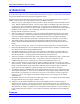
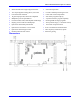
The PMAC Mini PCI is an inexpensive, compact 2-axis version of the PMAC family.
It can be used in a PC’s PCI slot as a half-sized board (230 mm, 9” long) or it can be used as a standalone
using serial communications for setup and/or application control.
Programs for the PMAC Mini PCI, both motion and PLC, are 100% compatible with other versions of
PMAC. However, there are several features unique to the PMAC Mini PCI:
1. There are only two output digital-to-analog converters: DAC1 and DAC2 (DAC3 and DAC4 do not
exist). Both have differential outputs. The two analog outputs on the PMAC Mini PCI can be used
as velocity or torque commands for separate axes, or as phase current commands for a single axis
commutated by the card. However, there are four incremental encoder interfaces that can be used for
feedback or master positions. Two of these may alternately be used to process analog voltages
through optional on-board V/F converters.
2. There is no JPAN control panel port. There are no digital inputs dedicated to the functions of this
port on other PMACs. To obtain equivalent functions, general-purpose inputs must be used along
with a PLC program reading these inputs. Handwheel encoders may be brought in through the
JMACH port. Wiper inputs may be brought in through the JAUX port if Option 15 is purchased.
3. The memory mapping of the general-purpose digital I/O is different from other versions of the
PMAC. Different M-Variable definitions are required for these I/Os on the PMAC Mini PCI (see
below).
4. The serial port is RS-232 only. There is no on-board or optional capability to use RS-422 format.
5. Dual-ported RAM (Option 2) is an on-board option that must be factory-installed. The PMAC Mini
PCI cannot use the separate Option 2 DPRAM board.
6. The JTHW multiplexer port outputs are not as powerful as on other PMACs. There should be no
more than one meter (three feet) of cable to any device on the port, instead of the three meters (ten
feet) on other PMACs. Anything longer should use the Acc-35A driver board.
7. There are no jumpers to control the open-circuit voltage of the complementary inputs. Instead, there
are removable socketed SIP resistor packs. At the factory, these are configured to tie the
complementary lines to 2.5V. Removed, they will tie the complementary lines to 5V.
8. There is no JXIO connector to provide clock signals to mating connectors on Acc-24P or Acc-8D
Option 8 boards. If either of these boards is used with the PMAC Mini PCI, a custom cable should be
made to connect the DCLK signal on the PMAC Mini PCI J7 port to both the DCLK and SCLK
inputs on the Acc-24P JXIO port, or the SCLK input on the Acc-8D Option 8 JXIO port.
9. The HMFLn, PLIMn, and MLIMn flag inputs on the PMAC Mini PCI can accept signals from both
sourcing and sinking drivers. If the A+15V on JMACH is used to supply the flag isolators through
E89 and E90, only sinking drivers can be used. But, if pin 13 on J8 (JAUX) is used to supply the
isolators, a +12V to +24V supply can be used for sinking drivers, or a 0V supply can be used for
sourcing drivers.
10. The PMAC Mini PCI has an interlock circuit that drops out the +/-15V supplies to the analog outputs
through a fail-safe relay if any supply on PMAC is lost.
11. If Option 15 is purchased, the PMAC Mini PCI has the capability for two on-board voltage-to-
frequency (V/F) converters. These may be used for two Wiper analog inputs, or to convert the two
analog outputs to pulse trains for stepper-type drives. The V/F converters can each take an input of 0-
10V referenced to AGND. The pulse trains can be tied into encoder channels 3 or 4 for counting. (It
is also possible, but more expensive, to use the first two channels of the off-board Acc-8D Option 2
board.)
Features