
Reference Manual


PMAC Mini PCI Hardware Reference Manual
38 Connector Pinouts
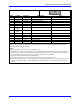
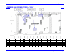
J11 JMACH (60-Pin Header)
-Continued
Pin # Symbol Function Description Notes
45 DAC1/ Output Ana. Out Neg. 1 4,5
46 DAC2/ Output Ana. Out Neg. 2 4,5
47 AENA1/DIR1 Output Amp.-Ena/Dir. 1 6
48 AENA2/DIR2 Output Amp.-Ena/Dir. 2 6
49 FAULT1 Input Amp.-Fault 1 7
50 FAULT2 Input Amp.-Fault 2 7
51 MLIM1 Input Neg. End Limit 1 8,9
52 MLIM2 Input Neg. End Limit 2 8,9
53 PLIM1 Input Pos. End Limit 1 8,9
54 PLIM2 Input Pos. End Limit 2 8,9
55 HMFL1 Input Home-Flag 1 10
56 HMFL2 Input Home-Flag 2 10
57 FEFCO/ Output Watchdog Out Indicator/Driver
58 AGND Input Analog Common
59 A+15V/OPT+V Input Analog +15V Supply
60 A-15V Input Analog -15V Supply
The J11 connector is used to connect PMAC to the servo amps, flags, and encoders.
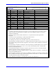
Notes:
1. In standalone applications, these lines can be used as +5V power supply inputs to power PMAC’s digital
circuitry. However, if a terminal block is available on the version of PMAC, bring the +5V power in
through the terminal block.
2. Referenced to digital common (GND). Maximum of + 12V permitted between this signal and its
complement.
3. If not used, leave this input floating (i.e. digital single-ended encoders).
4. + 10V, 10mA max, referenced to analog common (AGND).
5. Leave floating if not used; do not tie to AGND. In this case, AGND is the return line.
6. Functional polarity controlled by jumper E17. Sinking/sourcing nature of output control by IC type in U44
socket (default sinking) and E101/E102 configuration. Choice between AENA and DIR use controlled by
Ix02 and Ix25.
7. Functional polarity controlled by variable Ix25. Must be conducting to AGND (sinking driver) to produce a
0 in PMAC software. Pull-up is to A+15V or A+V (12-24V) as determined by E100. Automatic fault
function can be disabled with Ix25.
8. Pins marked PLIMn should be connected to switches at the positive end of travel. Pins marked MLIMn
should be connected to switches at the negative end of travel.
9. Must be conducting to 0V (usually AGND) for PMAC to consider itself not into this limit. Automatic limit
function can be disabled with Ix25.
10. Functional polarity for homing or other trigger use of HMFLn controlled by Encoder/Flag Variable 2 (I902,
I907, etc.) HMFLn selected for trigger by Encoder/Flag Variable 3 (I903, I908, etc.). Must be conducting to
0V (usually AGND) to produce a 0 in PMAC software.
11. If DAC calibration is needed, R37 is for offset DAC1, and R41 is for offset DAC2.