
Reference Manual


PMAC Mini PCI Hardware Reference Manual
36 Connector Pinouts
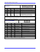
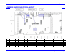
J8 JAUX (14-Pin Header)
Front View
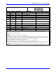
Pin # Symbol Function Description Notes
1 WIPER1 Input 0-10V Analog Input 1, 2
2 WIPER2 Input 0-10V Analog Input 1, 2
3 AGND Common Analog/Flag Common
4 AGND Common Analog/Flag Common
5 EQU1/ Output Enc. 1 Position Compare 3
6 EQU2/ Output Enc. 2 Position Compare 3
7 AENA1/
DIR1
Output Amp. 1 Enable/Direction 3,4,5
8 AENA2/
DIR2
Output Amp. 2 Enable/Direction 3,4,5
9 PULSE1 Output Chan. 1 Pulse Command 1,3
10 PULSE2 Output Chan. 2 Pulse Command 1,3
11 FEFCO/ Output Watchdog Output 3
12 AGND Common Analog/Flag Common
13 A+V/FRET Input Flag Supply Volt 6
14 A-15V I/O Analog Minus Supply
This connector provides auxiliary signals for the PMAC Mini PCI, including analog inputs, position compare
outputs, pulse-and-direction outputs, and a flag supply/return voltage. All signals are referenced to AGND,
isolated from the 5V digital circuitry.
Notes:
1. Requires Option 15 V/F Converters be installed to use.
2. WIPER1 is tied to DAC1 if jumper E110 is installed; WIPER2 is tied to DAC2 if jumper E113 is installed.
3. Open-collector sinking output in standard configuration (ULN2803A in U44); Can be replaced with sourcing
driver (UDN2981A) in U44 socket; 100 mA per point sinking/sourcing capability.
4. Function of this signal determined by Ix02 and Ix25.
5. Can be tied to Encoder 3 or 4 feedback with jumpers (see E111, E112, E114, E115).
6. With jumper E89 ON, tied to A+15V from J11 pin 59; with E89 OFF and E90 at 1-2, can be separate +12V to
+24V for input flags (HMFLn, PLIMn, MLIMn) with sinking drivers, or 0V for input flags with sourcing
drivers.