
Reference Manual


PMAC-Mini PCI Hardware Reference Manual
E-Point Jumper Descriptions 27
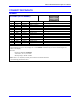
E101 - E102: Amplifier Enable Output Configure
E-Point and
Physical Layout
Location Description Default
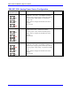
E100
B2
Jump pin 1 to 2 to apply A+15V from J11 pin 59 to pin 1 of
E101, pin 3 of E102, and FAULT input flag return. This
makes U44 AENA/ EQU / PULSE / DIR / FEFCO driver IC
work from analog A+15V supply.
Jump pin 2 to 3 to apply A+V (12-24V) from J8 pin 13 to pin
1 of E101, pin 3 of E102, and FAULT input flag return. This
makes U44 AENA/EQU/PULSE/DIR/FEFCO driver IC work
from separate A+V (12-24V) supply. (This cannot be used
when A+V is brought from digital side through E85.)
1-2 Jumper
installed
E101
B2
Jump pin 1 to 2 to apply A+15V/A+V (as set by E100) to pin
11 of U44 AENAn and EQUn driver IC (should be
ULN2803A for sink output configuration).
Jump pin 2 to 3 to apply GND to pin 11 of U44 (should be
UDN2981A for source output configuration).
1-2 Jumper
installed
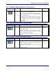
E102
B2
Jump pin 1 to 2 to apply GND to pin 11 of U44 AENAn and
EQUn (should be ULN2803A for sink output configuration).
Jump pin 2 to 3 to apply A+15V/A+V (as set by E100) to pin
11 of U44 (should be UDN2981A for source output
configuration).
1-2 Jumper
installed
Note: E100, E101 and E102 must number in the same direction
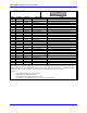
E110 - E115: V/F Converter Configuration
(Voltage-to-Frequency Converter Option [OPT 15] Required)
E-Point and
Physical Layout
Location Description Default
E110
B1
Jump pin 1 to 2 to tie DAC1 output to WIPER1 input (stepper
drive).
Remove jumper to keep lines separate.
No jumper
installed
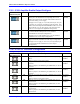
E111
B1
Jump pin 1 to 2 to set 10kHz/V gain (100kHz max) on 1st V/F
converter.
Remove jumper to set 200kHz/V gain (2MHz max) on 1st V/F
converter.
No jumper
installed
E112
B1
Jump pin 1 to 2 to set 10kHz/V gain (100kHz max) on 1st V/F
converter.
Remove jumper to set 200kHz/V gain (2MHz max) on 1st V/F
converter.
No jumper
installed
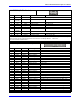
E113
B2
Jump pin 1 to 2 to tie DAC2 output to WIPER2 input (stepper
drive).
Remove jumper to keep lines separate.
No jumper
installed
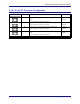
E114
B2
Jump pin 1 to 2 to set 10kHz/V gain (100kHz max) on 2nd
V/F converter.
Remove jumper to set 200kHz/V gain (2MHz max) on 2nd
V/F converter.
No jumper
installed
E115
B2
Jump pin 1 to 2 to set 10kHz/V gain (100kHz max) on 2nd
V/F converter.
Remove jumper to set 200kHz/V gain (2MHz max) on 2nd
V/F converter.
No jumper
installed