
Reference Manual


PMAC Mini PCI Hardware Reference Manual
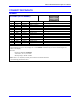
26 E-Point Jumper Descriptions
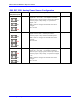
E89: Amplifier-Supplied Switch Pull-Up Enable
E-Point and
Physical Layout
Location Description Default
E89
A1
Jump pin 1 to 2 to allow A+V on J8 (JAUX) pin 13, to
tie to A+15V on J11 (JMACH1) pin 59.
Remove jumper to permit separate voltage supply from
A+V for input flags (+12V to +24V for sinking drivers,
0V for sourcing drivers).
This jumper must be installed to allow A+15V to power
the OPTO switch sensor inputs (including limits) from
the same OPTO-power supply that powers the amplifier
output stage.
Also see E90.
Jumper
installed
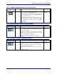
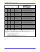
E90: Host-Supplied Switch Pull-Up Enable
E-Point and
Physical Layout
Location Description Default
E90
A1
Jump pin 1 to 2 to allow A+V/FRET on J8 pin 13 and/or
J11 pin 59 (also see E89), to power OPTO switch sensor
inputs (including limits).
Jump pin 2 to 3 to allow +12V from DC bus connector P1-
pin B09 to power "OPTO" switch sensor inputs (including
limits). Optical isolation is then lost.
Also see E85, E87, E88 and PMAC opto-isolation
diagram.
1-2 Jumper
installed
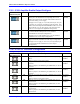
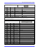
E98: DAC/ADC Clock Frequency Control
E-Point and
Physical Layout
Location Description Default
E98
C2
Jump 1-2 to provide a 2.45 MHz DCLK signal to DACs
and ADCs. Jump 2-3 to provide a 1.23 MHz DCLK signal
to DACs and ADCs. Important for high accuracy A/D
conversion on Acc-28A boards.
Note: This also divides the phase and servo clock freq. in
half.
See E29-E33, E3-E6
1-2 Jumper
installed