
Reference Manual


PMAC-Mini PCI Hardware Reference Manual
E-Point Jumper Descriptions 21
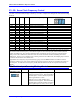
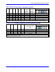
E17A - E17D: Amplifier-Enable/Direction Polarity Control
E-Point and
Physical Layout
Location Description Default
E17A
A3
Jump 1-2 for high TRUE AENA1.
Remove jumper for low TRUE AENA1.
No jumper installed
E17B
A3
Jump 1-2 for high TRUE AENA2.
Remove jumper for low TRUE AENA2.
No jumper installed
E17C
A3
Jump 1-2 for high TRUE AENA3.
Remove jumper for low TRUE AENA3.
No jumper installed
E17D
A3
Jump 1-2 for high TRUE AENA4.
Remove jumper for low TRUE AENA4.
No jumper installed
Low-true enable is the fail-safe option with the default sinking (open-collector) ULN2803A output driver IC in
U44. If U44 is replaced with a UDN2981A sourcing driver IC (and E101 and E102 are changed), high-true
enable is the fail-safe option.
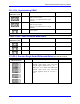
E19: Watchdog Disable
E-Point and
Physical Layout
Location Description Default
E19
F1
Jump pin 1 to 2 to disable Watchdog timer (for
test purposes only).
Remove jumper to enable Watchdog timer.
No jumper installed
E20 - E22: Flash Firmware Bank Select
E-Point and
Physical Layout
Location Description Default
E20
G3
Power Up/Reset Load Source Jumper 1. No jumper installed
E21
G3
Power Up/Reset Load Source Jumper 2.
Install to read flash IC on power-up/ reset.
Jumper installed
E22
G3
Power Up/Reset Load Source Jumper 3.
Install to read flash IC on power-up/ reset.
Jumper installed
Other combinations are for factory use only; the board will not operate in any other configuration
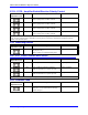
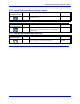
E23: Firmware Load
E-Point and
Physical Layout
Location Description Default
E23
G3
Remove jumper for normal operation.
Jump pin 1 to 2 to reload firmware through
serial or bus port.
No jumper installed