
Reference Manual


PMAC Mini PCI Hardware Reference Manual
20 E-Point Jumper Descriptions
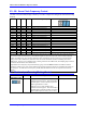
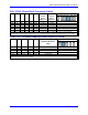
E8 – E10: Synchronizing PMAC
E-Point and
Physical Layout
Location Description Default
E8
C1
Jump pin 1-2 for NULL modem connection
(DTR connects to DSR).
Jump pin 2-3 for differential Phase signal
(PHASE/).
No jumper installed
E9
C1
Jump pin 1-2 for NULL modem connection
(DTR connects to DSR).
Jump pin 2-3 for differential Servo signal
(SERVO/).
No jumper installed
E10
E1
Jump pin 1-2 to select to receive external
clocks CARD0.
No jumper installed
Note: Jumpers E8 and E9 must have the same settings.
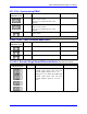
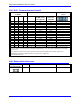
E10A - E10C: Flash Firmware Bank Select
E-Point and
Physical Layout
Location Description Default
E10A
G2
Flash firmware bank, select jumper 1. No jumper installed
E10B
G2
Flash firmware bank, select jumper 2. No jumper installed
E10C
G2
Flash firmware bank, select jumper 3. No jumper installed
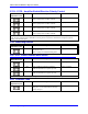
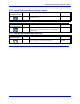
E11-E14: Encoder Single Ended/Differential Select (Note: REV-103 and above)
E Point and
Physical Layout
Location Description Default
E11
E12
E13
E14
Jump pin 2 to 3 to obtain differential
encoder input mode. This will bias
encoder negative inputs to VCC = 5V
Jump pin 1 to 2 to obtain non-differential
encoder input mode. This will bias
encoder negative inputs to 1/2 VCC =
2.5V
1-2 Jumper installed