
Reference Manual


PMAC Mini PCI Hardware Reference Manual
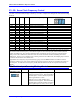
18 E-Point Jumper Descriptions
E-POINT JUMPER DESCRIPTIONS
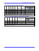
E0: Reserved for Future Use
E-Point and
Physical Layout
Location Description Default
E0
F1
Reserved for future use No jumper
installed
Warning:
The jumper setting must match the type of driver IC, or damage to the IC will result.
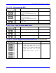
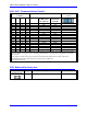
E1 - E2: Machine Output Supply Voltage Configure
E-Point and
Physical Layout
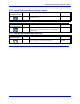
Location Description Default
E1
E1
Jump pin 1 to 2 to apply +V (+5V to 24V) to pin 10
of U55 (should be ULN2803A for sink output
configuration) JOPTO Machine outputs M01-M08.
Jump pin 2 to 3 to apply GND to pin 10 of U55
(should be UDN2981A for source output
configuration).
Also see E2.
1-2 Jumper
installed
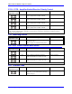
E2
E1
Jump pin 1 to 2 to apply GND to pin 9 of U55 (should
be ULN2803A for sink output configuration).
Jump pin 2 to 3 to apply +V (+5V to 24V) to pin 9 of
"U55" (should be UDN2981A for source output
configuration).
Also see E1.
1-2 Jumper
installed
Note: E1 and E2 must number in the same direction.