
Reference Manual


PMAC-Mini PCI Hardware Reference Manual
Option 15 — Voltage to Frequency Converter 13
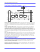
Configuration as Analog Input with a 0-2 MHz Frequency Range
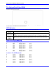
Jumpers Setting
Input 1 Input 2
E110 E111 E112 E116 E117 E113 E114 E115 E118 E119
OFF OFF OFF ON ON OFF OFF OFF ON ON
E34 - E37: Encoder Sampling Clock Frequency Control
E34A E34 E35 E36 E37 SCLK Clock Frequency
ON OFF OFF OFF OFF 19.6608 MHz
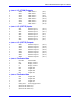
Software configuration to be typed on the terminal window:
WY$0724,$40722,64 ;Timebase Encoder Conversion entry for Input #1
WY$0726,$40723,64 ;Timebase Encoder Conversion entry for Input #2
I911=1 ;Encoder 3 digital delay filter disabled (bypassed)
I916=1 ;Encoder 4 digital delay filter disabled (bypassed)
I910=4 ;Encoder channel 3 for pulse-and-direction decode
;(Input #1)
I915=4 ;Encoder channel 4 for pulse-and-direction decode
;(Input #2)
M34->X:$0725,24 ;Result of the analog conversion. The range of
;M34 is from 0 to the I10 value, proportional
;to the 0-10V range on the analog input #1.
M35->X:$0727,24 ;Result of the analog conversion. The range of
;M35 is from 0 to the I10 value, proportional to
;the 0-10V range on the analog input #2.
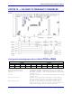
General Configuration for Step and Direction Outputs
• Set the appropriate jumpers as shown in the diagrams below.
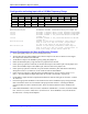
• Wire the PULSEn and AENAn/DIRn open-collector outputs on the JAUX connector to the stepper
drive inputs with AGND as the reference.
• Tie the DACn output to the WIPERn input by putting the jumper on.
• Select the desired frequency range with the two jumpers for the channel.
• If true open-loop operation is desired, tie the PULSEn output to the CHAm input with the jumper and
tie the AENAn/DIRn output to the CHBm input; otherwise leave these jumpers off.
• If true open-loop operation is desired, set up the encoder channel for pulse-and-direction decode by
setting I910 or I915 to 4; otherwise, use as normal for real encoder feedback.
• If true open-loop operation is desired and the 0-2 MHz frequency range is selected, set I911=1 or
I916=1. This will disable the digital delay filter for Encoder 3 or Encoder 4, respectively.
• Put the PMAC output channel in magnitude-and-direction mode by setting bit 16 of Ix02 to 1 and bit
16 of Ix25 to 1
• Choose the appropriate simulated or real encoder for the motor’s feedback loop by setting Ix03 and
Ix04 to the address in the conversion table of the proper encoder channel. Assuming the default
conversion table, the value is $0720 for ENC1, $0721 for ENC2, $0722 for ENC3, and $0723 for
ENC4.
• If the simulated feedback is used, set Ix30 to 550,000 for 100 kHz max.; or Ix30 to 27,500 for 2 MHz
max. Set Ix31 to 0, Ix32 to 1000, Ix33 to 0, and Ix35 to 0. If real feedback is used, tune the motor
the same as for a velocity-mode amplifier.