
Reference Manual


PMAC-Mini PCI Hardware Reference Manual
Hardware Setup 9
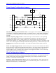
The Optional Dual-Ported RAM
When the PMAC Mini PCI Option 2 is ordered, U20 is installed on-board at the factory. The DPRAM is
located on the back of the board.
See the PMAC User Manual for more information.
LED Indicators
The PMAC Mini PCI has two sets (front side and back) of three LED indicators.
D9 and D9A
(green)
When the green LED is lit, this indicates that power is applied to the +5V input and it is good.
D10 and
D10A (red)
When the red LED is lit, this indicates that the watchdog timer has tripped and shut down the
PMAC.
D19 and
D19A
(yellow)
The PMAC Mini PCI has an interlock circuit that drops out the +/-15V supplies to the analog
outputs through a fail-safe relay if any supply on PMAC is lost. In this case, the LED will be
off.
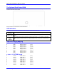
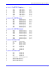
Input and Output Mapping
Y:$FFC0 J1 (JDISP) Outputs
0 DB0 Display Data 0 (J1-8)
1 DB1 Display Data 1 (J1-7)
2 DB2 Display Data 2 (J1-10)
3 DB3 Display Data 3 (J1-9)
4 DB4 Display Data 4 (J1-12)
5 DB5 Display Data 5 (J1-11)
6 DB6 Display Data 6 (J1-14)
7 DB7 Display Data 7 (J1-13)
Y:$FFC1 J3 (JTHW) Inputs
0 DAT0 THW Data 0 (J3-3)
1 DAT1 THW Data 1 (J3-5)
2 DAT2 THW Data 2 (J3-7)
3 DAT3 THW Data 3 (J3-9)
4 DAT4 THW Data 4 (J3-11)
5 DAT5 THW Data 5 (J3-13)
6 DAT6 THW Data 6 (J3-15)
7 DAT7 THW Data 7 (J3-17)