
Reference Manual


PMAC-Mini PCI Hardware Reference Manual
Hardware Setup 7
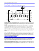
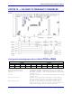
Board Reset/Save Jumpers
E50: Flash-Save Enable/Disable Control – If E50 is on (default), the active software configuration of
the PMAC can be stored to non-volatile flash memory with the SAVE command. If the jumper on E50 is
removed, this SAVE function is disabled and the contents of the flash memory cannot be changed.
E51: Re-Initialization on Reset Control – If E51 is off (default), PMAC executes a normal reset,
loading active memory from the last saved configuration in non-volatile flash memory. If E51 is on,
PMAC re-initializes on reset, loading active memory with the factory default values.
Communication Jumpers
PCI Bus Base Address Control – The selection of the base address of the card in the I/O space of the
host PC’s expansion bus is assigned automatically by the operating system and it is not selected through a
jumper configuration.
E44-E47: Serial Baud Rate Selection – The serial baud rate is determined by a combination of the
setting of jumpers E44-E47 and the CPU frequency on a PMAC board. If the CPU’s operational
frequency has been determined by a non-zero setting of I46, the serial communications baud rate is
determined at power-up/reset by variable I54 alone. Currently, the Flex CPU’s serial baud rate is
determined at power-up/reset by variable I54 alone.
E49: Serial Communications Parity Control – Jump pin 1 to 2 for no serial parity. Remove jumper for
odd serial parity.
Reserved Configuration Jumpers
E0: Reserved for future use.
E48: Reserved for future use.
I/O Configuration Jumpers
Warning:
A wrong setting of these jumpers will damage the associated output IC.
E1-E2: Machine Output Supply Configure – With the default sinking output driver IC (ULN2803A or
equivalent) in U55 for the J5 JOPTO port outputs, these jumpers must connect pins 1 and 2 to supply the
IC correctly. If this IC is replaced with a sourcing output driver IC (UDN2981A or equivalent), these
jumpers must be changed to connect pins 2 and 3 to supply the new IC correctly.
E7: Machine Input Source/Sink Control – With this jumper connecting pins 1 and 2 (default), the
machine input lines on the J5 JOPTO port are pulled up to +5V or the externally provided supply voltage
for the port. This configuration is suitable for sinking drivers. If the jumper is changed to connect pins 2
and 3, these lines are pulled down to GND. This configuration is suitable for sourcing drivers.
E17A - E17D: Motors 1-4 Amplifier-Enable Polarity Control – Jumpers E17A through E17D control
the polarity of the amplifier enable signal for the corresponding motor 1 to 4. When the jumper is on
(default), the amplifier-enable line for the corresponding motor is low true so the enable state is low-
voltage output and sinking current and the disable state is not conducting current. With the default
ULN2803A sinking driver used by the PMAC on U44, this is the fail-safe option, allowing the circuit to
fail in the disable state. With this jumper off, the amplifier-enable line is high true so the enable state is
not conducting current and the disable state is low-voltage output and sinking current. This setting is not
recommended.
Warning: