
Reference Manual


PMAC Mini PCI Hardware Reference Manual
6 Hardware Setup
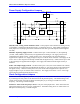
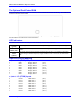
E34A-E37: Encoder Sample Clock – Only one of the jumpers E34A – E37 which select the encoder
sample clock frequency, may be on in any configuration. The frequency must be high enough to accept
the maximum true count rate (no more than one count in any clock period), but a lower frequency can
filter out longer noise spikes. The anti-noise digital delay filter can eliminate noise spikes up to one
sample-clock cycle wide.
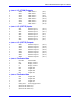
E98: DAC/ADC Clock Frequency Control – Leave E98 in its default setting of 1-2 which creates a
2.45 MHz DCLK signal, unless connecting an Acc-28 A/D-converter board. In this case, move the
jumper to connect pins 2 and 3 which creates a 1.22 MHz DCLK signal.
Encoder Configuration Jumpers
Encoder Complementary Line Control – PMAC has differential line receivers for each encoder
channel, but can accept either single-ended (one signal line per channel) or differential (two signal lines,
main and complementary, per channel).
REV 102 and below:
The selection of the type of encoder used, either single ended or differential, is
made through resistor packs configurations and not through jumper configurations: RP13, RP14, RP20
and RP21.
REV 103 and above:
The selection of the type of encoder used, either single ended or differential, is
made through jumper configurations: E11, E12, E13 and E14.
Single-Ended Encoders
With the jumper for an encoder set for single-ended, the differential input lines for that encoder are tied to
2.5V; the single signal line for each channel is then compared to this reference as it changes between 0
and 5V.
When using single-ended TTL-level digital encoders, the differential line input should be left open, not
grounded or tied high; this is required for The PMAC differential line receivers to work properly.
Differential Encoders
Differential encoder signals can enhance noise immunity by providing common-mode noise rejection.
Modern design standards virtually mandate their use for industrial systems, especially in the presence of
PWM power amplifiers, which generate a great deal of electromagnetic interference.
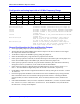
Connect pin 1 to 2 to tie differential line to +2.5V
• Tie to +2.5V when no connection
• Tie to +2.5V for single-ended encoders
Connect pin 2 to 3 to tie differential line to +5V
• Don’t care for differential line driver encoders
Tie to +5V for complementary open-collector encoders (obsolete)
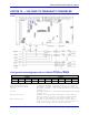
E117, E118: Wiper to Encoder Input Enable – Putting these jumpers on ties the output of the Option
10 voltage-to-frequency converter that can process the Wiper analog input on the JAUX port to the
Channel 3 (E117) or 4 (E118) encoder circuitry. If the frequency signal is connected to one of these
channels, no encoder should be connected through the JMACH1 connector.