
Specifications


MACRO CPU Board
12 3U MACRO CPU Jumper and Switch Configurations
Note:
Pin 1 of an E-point is masked by an "X" in white ink on the composite side, and by
a square solder pad on the solder side.
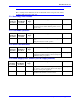
E1: Watchdog Timer Disable
Rev -105
and Later
Location
Rev -104
and Earlier
Location
Jumper
Type
Description Default
B-1 F-1 2-Pin Remove jumper to enable Watchdog Timer.
Jump pins 1 and 2 to disable Watchdog Timer (for test
purposes only)
Not jumpered
E2: CPU Mode Operation
Rev -105
and Later
Location
Rev -104
and Earlier
Location
Jumper
Type
Description Default
D-2 D-1 3-Pin Jump pins 1 and 2 for firmware download through serial
port.
Jump pins 2 and 3 for normal operation.
Pin 2-3
E3: Serial Port Baud Rate
Rev -105
and Later
Location
Rev -104
and Earlier
Location
Jumper
Type
Description Default
E-3 E-2 2-Pin Jump pins 1 and 2 for 9600-baud serial port operation.
(Required for Yaskawa interface). Remove jumper for
38400-baud serial port operation.
Not jumpered
E4: Power Supply-Loss Control (±15Vdc Supply Monitor)
Rev -105
and Later
Location
Rev -104
and Earlier
Location
Jumper
Type
Description Default
E-3 E-2 2-Pin Jump pins 1 and 2 to disable servo outputs on loss of
+5V, +15V, or –15V power supply. Remove this jumper
to monitor +5Vdc power supply only.
Not jumpered
±15V supply monitoring is not usually required for
applications without DACs or A-D converters.