
Specifications


MACRO CPU Board
3U MACRO CPU Board Hardware Setup 7
3U MACRO CPU BOARD HARDWARE SETUP
The hardware setup of the 3U MACRO CPU Board consists of the setting of 2 rotary switches, the setting of
several E-point jumpers on each board, followed by power supply and signal connections.
Note
E-Point Jumper numbers are shown in white ink on the legend of each board. Pin
numbers for each number can be determined either from the legend on the component
side on the board, or by looking at the solder side of the board, where pin 1 has a
square solder pad.
3U MACRO CPU Board Jumper & Switch Setup
The MACRO Station has two 16-way rotary switches on the MACRO CPU board that establish the
station’s basic configuration on the MACRO ring.
SW1 Rotary Switch Setting: SW1 establishes how many servo nodes, and which servo nodes, will be used
on the MACRO station. It also establishes the mapping of MACRO node numbers to MACRO Station
channel numbers. This mapping information will be important in establishing the software setup.
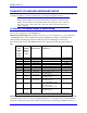
The following table shows possible MACRO Station axis configurations and the appropriate settings of
SW1:
# of
Servo
Chan’s
&
Nodes
Used
Which
MACR
O Servo
Nodes
Used
Stack Axis
Boards Used
Backplane (UMAC) Axis
Boards Used
SW1 Setting
2 0, 1 1x ACC-1E -- 8
2 4, 5 1x ACC-1E -- 9
2 8, 9 1x ACC-1E -- 10 ($A)
2 12, 13 1x ACC-1E -- 11 ($B)
2 0, 1 1x ACC-2E* 1x ACC-24E2x or 51E 2
2 4, 5 1x ACC-2E* 1x ACC-24E2x or 51E 3
2 8, 9 1x ACC-2E* 1x ACC-24E2x or 51E 4
2 12, 13 1x ACC-2E* 1x ACC-24E2x or 51E 5
4 0, 1, 4, 5 1x ACC-2E 1x ACC-24E2x w/ Opt 1x or 1x
ACC-51E w/ Opt 1
0
4 8, 9, 12,
13
1x ACC-2E 1x ACC-24E2x w/ Opt 1x or 1x
ACC-51E w/ Opt 1
1
6 0, 1, 4, 5,
8, 9
1x ACC-1E,
1x ACC-2E
1x ACC-24E2x w/ Opt 1x or 1x
ACC-51E w/ Opt 1;
Plus 1x ACC-24E2x or 51E
12 ($C)
6 0, 1, 4, 5,
8, 9
2x ACC-2E* 1x ACC-24E2x w/ Opt 1x or 1x
ACC-51E w/ Opt 1;
Plus 1x ACC-24E2x or 51E
6
8 0, 1, 4, 5,
8, 9, 12,
13
2x ACC-2E 2x ACC-24E2x w/ Opt 1x /
ACC-51E w/ Opt 1
7
More detailed information on the SW1 settings is presented in the Jumper/Switch description in the
SW2 Rotary Switch Setting: SW2 establishes the number of the master IC to which the MACRO station will
respond. The values of 0 to 15 correspond to Master numbers 0 to 15, respectively. For a non-Turbo PMAC2
master, this value must match the master number value in the first hexadecimal digit of PMAC2’s I996. For a