
User's Manual


Geo MACRO Drive User and Reference Manual
Setting Up Turbo PMAC Conversion Table 77
SETTING UP THE TURBO PMAC CONVERSION TABLE
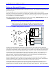
The position feedback from the Geo MACRO drive must be processed in the Turbo PMAC’s encoder
conversion table (ECT) before it can be used for servo purposes, such as position or velocity loop
feedback. The position feedback, whether primary or secondary, appears in the 24-bit Register 0 for the
servo node used. This is mapped as a Y-register in the Turbo PMAC, and the servo tasks can only access
X-registers for their source data.
So the primary purpose of the Turbo PMAC ECT entries for processing feedback from the Geo MACRO
drive is to move the data from the Y-registers in the MACRO ICs to X-registers in RAM, where they can
quickly be accessed by servo tasks, without requiring other processing.
This task is accomplished by conversion method “$2”: parallel read of a Y-register, no filtering.
Typically, the data from the Geo MACRO drive has already been shifted the standard 5 bits, so the
standard shifting in the ECT can be disabled by setting bit 19 of the first setup word (first I-variable of the
entry) to 1. This makes the method word $280000 + {Node Register 0 address}.
The second and last line (I-variable) of the entry should be set to $018000. The “018” (hexadecimal)
specifies that all 24 bits of the source register be used; the “000” specifies that the bits used start at bit 0.
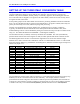
The following table shows an ECT in which the first eight entries are conversions of the first eight
MACRO servo nodes. Note have the combination of the bit 19 “shift disable bit and the “7” in the second
digit of the register address (e.g. $078420 for Node 0 Register 0) make the second hex digit of setup word
of each entry equal to “F”.
I-Var. Setting Meaning Turbo PMAC Address
I8000 $2F8420 MACRO Node 0 Reg. 0 Read $003501
I8001 $018000 24 bits, bit 0 LSB $003502
I8002 $2F8424 MACRO Node 1 Reg. 0 Read $003503
I8003 $018000 24 bits, bit 0 LSB $003504
I8004 $2F8428 MACRO Node 4 Reg. 0 Read $003505
I8005 $018000 24 bits, bit 0 LSB $003506
I8006 $2F842C MACRO Node 5 Reg. 0 Read $003507
I8007 $018000 24 bits, bit 0 LSB $003508
I8008 $2F8430 MACRO Node 8 Reg. 0 Read $003509
I8009 $018000 24 bits, bit 0 LSB $00350A
I8010 $2F8434 MACRO Node 9 Reg. 0 Read $00350B
I8011 $018000 24 bits, bit 0 LSB $00350C
I8012 $2F8438 MACRO Node 12 Reg. 0 Read $00350D
I8013 $018000 24 bits, bit 0 LSB $00350E
I8014 $2F843C MACRO Node 13 Reg. 0 Read $00350F
I8015 $018000 24 bits, bit 0 LSB $003510
The I-variables that use the results of the conversions (e.g. Ixx03 and Ixx04 for position and velocity-loop
feedback) will be set to the address of the last line of the entry. For example, if Motor 1 used the
processed data for Node 0 Register 0 from the above table for position-loop feedback, I103 would be set
to $3502. It is also possible to set these variables by specifying that you want to use the address of the last
I-variable in the entry. The command I103=@I8001 performs the same action as I103=$3502.