
User's Manual


Geo MACRO Drive User and Reference Manual
Setting Up Primary Feedback 71
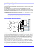
The commutation uses the hardware counter. There are 8000 hardware counts per revolution, and two
commutation cycles per revolution of the 4-pole motor. Therefore, Ixx70 will be set to 2, and Ixx71 will
be set to 8000. Ixx83 will contain the address of the hardware counter’s phase capture register.
For the servo, the interpolated results of the conversion table are used. There are 128 software counts per
line, or 256,000 software counts per revolution. With each revolution corresponding to 5 mm on the
screw, there are 51,200 software counts per millimeter. The measurement resolution, at 4096 states per
line, is 1/8,192,000 of a revolution, or 1/1,638,400 of a millimeter (~0.6 nanometers/state).
Example 2:
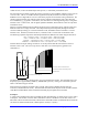
A linear brushless motor has a commutation cycle of 60.96 mm (2.4 inches). It has a linear scale with a
20-micron line pitch. The scale is used for both commutation and servo feedback. The user first needs to
set MS<node>,MI101=6 and/or MS<node>,MI102=6 for sinusoidal encoder. If needed the direction
decode can also be reversed with MS<node>,MI910 equal to 3 (CW) or 7 (CCW)
The commutation uses the hardware counter. There are 200 hardware counts per millimeter (5 microns
per count), so 12,192 hardware counts per commutation cycle. Ixx70 should be set to 1, and Ixx71 should
be set to 12,192.
The servo uses the interpolated results of the conversion table. With 128 software counts per line, and 50
lines per millimeter, there are 6400 software counts per millimeter (or 162,560 software counts per inch).
The measurement resolution, at 4096 states per line, is 204,800 states per mm (~5 nanometers/state).