
User's Manual


Geo MACRO Drive User Manual
68 Setting Up Primary Feedback
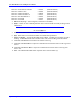
The user needs to set the control word MS<node>,MI930 (channel#1) and MS<node>,MI931
(channel#2) depending on the SSI encoder that the system uses, the control word specifies the mode that
the data are coming back to the PMAC (binary or gray code) and the length of the word.
• A 12-bit numeric binary encoder would mean the control word (MI930/MI931) need to be set equal
to $2, if the encoder is outputting gray code then the control word needs to be set equal to $3.
• A 16-bit numeric binary encoder would mean the control word (MI930/MI931) need to be set equal
to $6, if the encoder is outputting gray code then the control word needs to be set equal to $7.
• A 20-bit numeric binary encoder would mean the control word (MI930/MI931) need to be set equal
to $A, if the encoder is outputting gray code then the control word needs to be set equal to $B.
• A 24-bit numeric binary encoder would mean the control word (MI930/MI931) need to be set equal
to $E, if the encoder is outputting gray code then the control word needs to be set equal to $F.
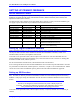
And the second I-variable the user needs to set is the clock output (frequency) to the SSI- encoder
interface (MS<node>, MI933). A value of 0 sets the Clock output @ 153.6 KHz. If higher clock
frequency required then MI933 can be set equal to 1 which sets the clock output @ 307.2 KHz, while a
value of 2 sets the clock output @ 614.4 KHz to the SSI-encoder interface. And the highest value the
clock can be set would be when MI933=3 setting the clock output @1.23MHz. MI933 is setting the clock
output for both channels #1 and #2, so user can not have different excitation frequencies for his two SSI-
interface encoders.
SSI encoders (especially multi-turn) generally provide absolute position information that eliminates the
need for a homing-search move to establish a position reference.