
User's Manual


Geo MACRO Drive User and Reference Manual
Setting Up Primary Feedback 67
SETTING UP PRIMARY FEEDBACK
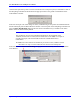
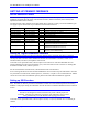
Device Selection Control
Geo Drives with the appropriate options can handle Quadrature Encoder Input (Shift / No Shift), Resolver
Feedback, Sinusoidal Encoder Input, SSI Absolute Encoders, ENDAT Interface (future release) and
Hiperface Interface (future release).
The main encoder input channels for the Geo PMAC Drive supports a variety of encoder feedback types.
5V supply to power the encoder is provided from each encoder connector.
Encoder #1 Encoder #2 Value Decode Function
MS{node},MI101 MS{node},MI102 0 Quadrature Encoder, Normal Shifting (1/T) (5-bits)
MS{node},MI101 MS{node},MI102 1 Quadrature Encoder, No shifting
MS{node},MI101 MS{node},MI102 2 SSI encoder, CW
MS{node},MI101 MS{node},MI102 3 SSI encoder, CCW
MS{node},MI101 MS{node},MI102 4 Resolver CW
MS{node},MI101 MS{node},MI102 5
Resolver CCW
MS{node},MI101 MS{node},MI102 6 Sinusoidal Encoder x4096
MS{node},MI101 MS{node},MI102 12 Write the arctangent value of the Sin and Cos to the
MACRO IO node (Resolver CCW +8)
MS{node},MI101 MS{node},MI102 13 Write the arctangent value of the Sin and Cos to the
MACRO IO node (Resolver CW +8)
MS{node},MI101 MS{node},MI102 14 Write the Sin and Cos values to the MACRO IO node
(Sin enc.) For troubleshooting
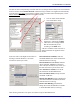
Setting up Digital Quadrature Encoders
Digital quadrature encoders are the most common position sensors used with Geo Drives. Interface
circuitry for these encoders comes standard on board-level Turbo PMAC controllers, UMAC axis-
interface boards, Geo drives, and QMAC control boxes.
User needs to set up his MS<node>, MI101 equal to 0 for channel #1 of his Geo MACRO drive for
normal quadrature encoder with 5-bit shifting (1/T). If the user doesn’t want to use the 1/T shifting then
he needs to set MS<node>, MI101 equal to 1.
For the second channel use MS<node>, MI102 and the same with channel #1.
So as to change the direction of the encoder feedback the user can either swap the cable leads or an easier
way would be to set MS<node>, MI910 equal to 3, clockwise, or equal to 7 for counterclockwise. MI910
can be set to more values for different options, please look at the Software Reference Appendix.
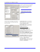
Setting up SSI Encoders
The Geo Drive will take the data from the SSI encoder and process it as a binary parallel word (12 or 24
bits). This data can then be processed in the PMAC encoder conversion table for position and velocity
feedback. With proper setup, the information can also be used to commutate brushless and AC induction
motors.
Caution:
Geo Drive was designed to work with either Gray Code or Binary Style SSI
Encoders. The Geo Drive takes the gray/binary code information and converts it
into a parallel binary word for absolute and ongoing position data
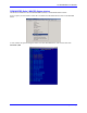
User needs to set up his MS<node>, MI101 equal to 2 (CW) or 3 (CCW) and then set 2 I-variables per
channel.