
User's Manual


Geo MACRO Drive User Manual
138 Geo Macro Drive MI-Variable Reference
MS{node},MI100 Motor Activation Control word
Range: 0 – $F
Units: none
Default: 0
MI100 controls which axis functions are enabled on the Geo MACRO drive.
If bit 0 (value of 1) is set to 1, this would indicate that the user wants to use only one motor node with his
Geo MACRO drive. This is always the case with single axis Geo MACRO Drives. If bit 0 is set to 0, then
both nodes are enabled (default).
Bit 1 is reserved for future use
If bit 2 (value of 4) is set to 1,then Motor #1 over-temperature function is enabled and Geo MACRO
Drive expects the Motor #1 Over-temperature input to be wired into pin 23 of the X1. If the over
temperature for motor #1 is triggered then the seven segment display will show the fault code “E5” or
“AE5” if in ASCII mode. If bit 2 is set to 0, Motor #1 over-temperature function is disabled (default).
If bit 3 (value of 8) is set to 1, then Motor #2 over-temperature function is enabled and Geo MACRO
Drive expects the Motor #2 Over-temperature input to be wired into pin 23 of the X2. If the over
temperature for motor #2 is triggered then the seven segment display will show the fault code “EA” or
“AEA” if in ASCII mode. If bit 3 is set to 0, Motor #2 over-temperature function is disabled.
This MI-variable is used at power-up/reset only, so to change its value and have the change take effect,
the user will change the value, issue an “MSSAVEn” command, and reset the Geo MACRO drive
(“MS$$$n” / power cycle).
For example, if we have a single axis Geo MACRO drive and we do not want to waste a motor node and
we want to have the Motor#1 over-temperature input enabled, then MS{node}, MI100=5
Note:
MS{node},MI100 was added in Geo MACRO firmware versions 1.006 and above.
MS{node},MI101-102 Primary Feedback Selection
MI101 determines what feedback device is used for primary feedback for Axis 1 on the Geo MACRO
drive. It defines what feedback register is copied into Feedback Register 0 for the main servo node for the
axis. MI102 performs the same function for Axis 2, if present and activated.
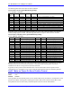
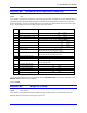
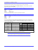
The following table shows the possible values for MI101 and MI102 and the feedback devices they select
for feedback.
Encoder #1 Encoder #2 Value Decode Function
MS{node},MI101 MS{node},MI102 0 Quadrature Encoder, Normal Shifting (1/T) (5-bits)
MS{node},MI101 MS{node},MI102 1 Quadrature Encoder, No shifting
MS{node},MI101 MS{node},MI102 2 SSI encoder, CW
MS{node},MI101 MS{node},MI102 3 SSI encoder, CCW
MS{node},MI101 MS{node},MI102 4 Resolver CW
MS{node},MI101 MS{node},MI102 5
Resolver CCW
MS{node},MI101 MS{node},MI102 6 Sinusoidal Encoder x4096
MS{node},MI101 MS{node},MI102
12 Write the arctangent value of the Sin and Cos to the
MACRO IO node (Resolver CCW +8)