
User's Manual


Geo MACRO Drive User and Reference Manual
Connectors 111
MACRO Link Connectors
The unit can be ordered to use either RJ45 connectors with twisted pair copper wires or a fiber optic
connection.
GMxxxxFx Fiber Optic MACRO Link
GMxxxxRx RJ-45 MACRO Link
In either case, there will be an input and an output connector and both are used to connect to the MACRO
link. The input connector is tied to the MACRO output connector of the previous device on the link. The
output connector connects to the input MACRO connector of the next device on the link.
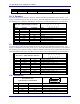
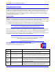
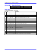
X5: MACRO I/O, MACRO Fiber Optic Transceiver (Optional)
Order Geo MACRO drive GMxxxxFx (F stands for Fiber Optic Macro Link).
J7
OPTO-XCVR
1
2
3
4
5
6
7
8
9
VEE
RD
RD
SD
VCC
VCC
TD
TD
VEE
GND_MAC
FIBER
XCVR
Double SC Fiber-Optic Socket
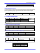
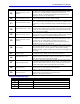
D20 is a MACRO LED which indicates the Link Activity.
LED Description
Green Activity, there is link
Red Link fault, no link. Check that the cables are correct in and out.
A bad cable can be the reason also.
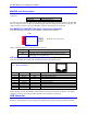
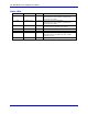
X10 and X11 MACRO RJ-45 Copper Connectors
Order Geo MACRO drive GMxxxxRx (R stands for RJ-45 Copper Macro Link).
X10 – MACRO Output Connector
X11 – Input Connector
Front View
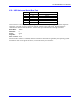
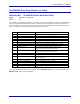
Pin # Symbol Function Description
1 DATA+ Data + Differential MACRO Signal.
2 DATA- Data - Differential MACRO Signal
3 Unused Unused terminated pin
4 Unused Unused terminated pin
5 Unused Unused terminated pin
6 Unused Unused terminated pin
7 Unused Unused terminated pin
8 Unused Unused terminated pin
The cable used for the MACRO wired connections is a CAT5 verified straight-through 8 conductor. The
input connector is tied to the MACRO output connector of the previous device on the link. The output
connector connects to the input MACRO connector of the next device on the link.
USB Connector
This connector is used to perform software diagnostic procedures or to download the operational
firmware. This connector is used in conjunction with the Pewin32 Pro or equivalent software package.