
User's Manual


Geo MACRO Drive User and Reference Manual
Connectors 109
8 N.C. Not Connected
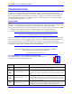
9 ANALOG1- Input Command level +/-10v
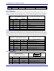
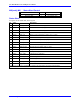
X8: S. Encoder 1
The Secondary Encoder channel #1 allows an external encoder to be fed back on the controller. A 5V
supply is available for the encoder power at pin 4. The three differential signal channels are brought into
the remaining pins as indicated. Standard for drives that use control board 603542 rev-10A and above.
X8 S. Enc. 1 (DB-9 Female Connector)
Pin # Symbol Function Notes
1 Cha1+ Input Secondary Encoder 1 A+
2 Chb1+ Input Secondary Encoder 1 B+
3 Index1+ Input Secondary Encoder 1 Index + /C+
4 5V Out Encoder Power
5 GND Out Common
6 Cha1- Input Secondary Encoder 1 A-
7 Chb1- Input Secondary Encoder 1 B-
8 Index1- Input Secondary Encoder 1 Index - /C-
9 N.C. Not Connected
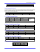
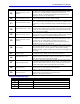
X9: S. Encoder 2
The Secondary Encoder channel #2 allows an external encoder to be fed back on the controller. A 5V
supply is available for the encoder power at pin 4. The three differential signal channels are brought into
the remaining pins as indicated. Need to enable the MACRO nodes MS{node}, I996 and the MACRO IC
nodes I6841/I6891/I6941/I6991. Standard for drives that use control board 603542 rev-10A and above.
X9 S. Enc. 2 (DB-9 female Connector)
Pin # Symbol Function Notes
1 Cha2+ Input Secondary Encoder 2 A+
2 Chb2+ Input Secondary Encoder 2 B+
3 Index2+ Input Secondary Encoder 2 Index + /C+
4 5V Out Encoder Power
5 GND Out Common
6 Cha2- Input Secondary Encoder 2 A-
7 Chb2- Input Secondary Encoder 2 B-
8 Index2- Input Secondary Encoder 2 Index - /C-
9 N.C. Not Connected
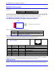
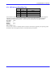
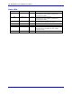
X13: Discrete I/O
X13: Discrete I/O,
6-pin Phoenix Terminal Block
651 2 3 4
Pin# Symbol Function Notes
1 +24V In/Out Interconnected with J4, 24VDC
2 24VRTN In/Out Interconnected with J4, 24VDC
3 +5V Output PMAC 5V
4 EQU1- Output Position Compare 1, 0V to 5V
5 EQU2- Output Position Compare 2, 0V to 5V