
User's Manual


Geo MACRO Drive User and Reference Manual
Setting Up Turbo Motor Operation 91
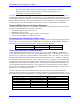
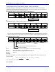
Hall Sensors at 30
o
,
150
o
, and 270
o
P179=I179 P129=I129 ; store previous offsets before test
#1o0 ; Open loop command of zero magnitude
Six Step Method U (M126) V(M125) W(M124)
I179=1500 I129=1500 ; -30
o
elec.
I179=3000 I129=-1500 ; 30
o
elec.
I179=1500 I129=-3000 ; 90
o
elec.
I179=-1500 I129=-1500 ; 150
o
elec.
I179=-3000 I129=1500 ; -150
o
elec.
I179=-1500 I129=3000 ; -90
o
elec.
I179=1500 I129=1500 ; -30
o
elec.
I179=P179 I129=P129 ; restore previous offsets after test
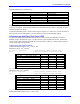
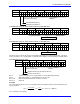
Hall Sensors at 0
o
,
120
o
, and 240
o
P179=I179 P129=I129 ; store previous offsets before test
#1o0 ; Open loop command of zero magnitude
Six Step Method U (Mx26) V(Mx25) W(Mx24)
I179=3000 I129=0 ; 0
o
elec.
I179=3000 I129= -3000 ; 60
o
elec.
I179=0 I129= -3000 ; 120
o
elec.
I179=-3000 I129=0 ; 180
o
elec.
I179=-3000 I129=3000 ; -120
o
elec.
I179=0 I129=3000 ; -60
o
elec.
I179=3000 I129=0 ; 0
o
elec.
I179=P179 I129=P129 ; restore previous offsets after test
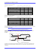
Now that the transitions have been mapped out for the sections of the electrical cycle, define and calculate
the Hall Effect Zero (HEZ).
Note:
Remember to clear the offsets when finished with this test.
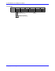
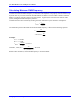
Hall Effect Zero (HEZ) – The Hall Effect Zero is the location in the electrical cycle when U is low
(value of 0), W is high (value of 1), and V changes state either from 1 to 0 or from 0 to 1.
Example:
U
V
W
-30 30 90 150 -150 -90
1
0
1
0
1
0
C
y
cle:
UVW Val ue: 1
3
2
6
4
5
HEZ @ +60 degrees electrical
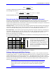
The offset can be computed using the mapping test shown above. In the example, the Hall Effect Zero
(HEZ) point was found to be between +30
o
e and +90
o
e, so it is called +60
o
e. The offset value can be
computed as: