
User's Manual


Geo MACRO Drive User and Reference Manual
Setting Up Turbo Motor Operation 89
of a short to motor power must be considered; safety considerations and industrial
design codes may make it impermissible to connect the signals directly to the
Turbo PMAC TTL inputs without isolation.
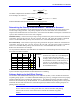
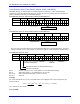
If used for servo position and velocity feedback, the three hall sensors are connected to the A, B, and C
encoder inputs, so that the signal edges can be counted. As with quadrature encoders, these inputs can be
single-ended or differential. They are not optically isolated inputs; if isolation is desired from the sensor,
this must be done externally. There may be applications in which the signals are connected both to U, V,
and W inputs (for power-on commutation position) and to A, B, and C inputs (for servo feedback).
Using Hall Effect Sensors for Phase Reference
There are usually four things to be considered about the alignment of the Hall Effect Sensors in order to
properly set up Hall Effect phasing within the Geo Drive.
• Commutation Phase angle –based on Ixx72
• Hall Effect Transition Points
• Hall Effect Zero position with respect to PMAC’s electrical zero
• Polarity of the Hall Effects – standard or reversed
Determining the Commutation Phase Angle
The commutation phase angle most likely has been set up already and it can be checked by querying the
value of Ixx72. For details on how this is determined, see the Turbo User Manual under Commutation
Phase angle for either Sinusoidal Commutation or Direct PWM Commutation.
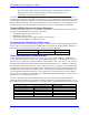
Turbo Ixx72=683 Turbo Ixx72=1365
Commutation Phase Angle
120 degrees 240 degrees
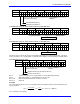
Finding the Hall Effect Transition Points
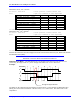
Usually, hall-effect sensors map out six zones of 60
°
elec each. In terms of PMAC2’s commutation
cycle, usually the boundaries will have one of two different combinations. If the Hall effect sensors are
placed at 30
°
, 150
°
, and 270
°
, then the boundaries will be located at 180
°
, -120
°
, -60
°
, 0
°
, 60
°
, and 120
°
.
Another common placement of Hall Effect Sensors has them located at 0
o
, 120
°
, and 240
°
. In this case,
the boundaries will be located at 30
°
, 90
°
, 150
°
, -150
°
, -90
°
, and -30
°
. Typically, a motor manufacturer
will align the sensors to within a few degrees of this, because these are the proper boundary points if all
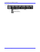
commutation is done from the commutation sensors. If mounting the hall-effect sensors manually, take
care to align the boundaries at these points. The simplest way is to force the motor to the zero degree
point with a current offset (as described below) and adjust the sensor while watching its outputs to get a
boundary as close as possible to this point.
In order to determine where the Hall effect transition points are located, there must be a method of
reading the status in software from the PMAC Executive Software or equivalent setup software. To do
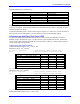
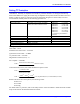
this, define M-variables to the Hall-Effects or equivalent inputs. Suggested definitions for Channel 1 are:
Turbo Ultralite Description
M124->X:$078420,0 M124->X:$003440,20
Channel 1 W flag
M125->X:$078420,1 M125->X:$003440,21
Channel 1 V flag
M126->X:$078420,2 M126->X:$003440,22
Channel 1 U flag
M127->X:$078420,3 M127->X:$003440,23
Channel 1 T flag
M128->X:$078420,0,4 M128->X:$003440,20,4
Channel 1 TUVW as a 4-bit value
M171->X:$00B4,0,24,S M171->X:$00B4,0,24,S
Channel 1 Phase Position Register
Note: Either addressing can be used with Geo MACRO drive.