^1 USER MANUAL & REFERENCE ^2 Geo MACRO Drive ^3 Direct PWM Amplifier over MACRO ^4 500-603701-xUxx ^5 April 27, 2010 Single Source Machine Control Power // Flexibility // Ease of Use 21314 Lassen Street Chatsworth, CA 91311 // Tel. (818) 998-2095 Fax. (818) 998-7807 // www.deltatau.
Copyright Information © 2010 Delta Tau Data Systems, Inc. All rights reserved. This document is furnished for the customers of Delta Tau Data Systems, Inc. Other uses are unauthorized without written permission of Delta Tau Data Systems, Inc. Information contained in this manual may be updated from time-to-time due to product improvements, etc., and may not conform in every respect to former issues. To report errors or inconsistencies, call or email: Delta Tau Data Systems, Inc.
After removing the power source from the equipment, wait at least 10 minutes before touching or disconnecting sections of the equipment that normally carry electrical charges (e.g., capacitors, contacts, screw connections). To be safe, measure the electrical contact points with a meter before touching the equipment. The following text formats are used in this manual to indicate a potential for personal injury or equipment damage.
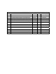
REVISION HISTORY REV. DESCRIPTION DATE CHG APPVD 1 UPDATED ENDAT SETUP INFO, P. 82 07/18/06 CP P.SHANTZ 2 UPDATED ERROR CODE EF GATE DRIVE INFO 09/21/06 CP P.SHANTZ 3 CORRECTED GP OUT INPUT FUNCTIONS, P. 39 06/11/08 CP K.ZHAO 4 CORRECTED RESET COMMAND, P. 138 10/30/08 CP S. MILICI 5 CORRECTED M-VARIABLE DEFINITIONS, P. 87 12/08/09 CP S. MILICI 6 CORRECTED ERRORS PPS. 85-87 02/25/10 CP S. MILICI 7 CORRECTED COVER PAGE FORMATTING 03/01/10 CP C.
Geo MACRO Drive User and Reference Manual Table of Contents Copyright Information................................................................................................................................................i Operating Conditions .................................................................................................................................................i Safety Instructions.................................................................................................
Geo MACRO Drive User Manual CE Filtering ........................................................................................................................................................30 Input Power Filtering .........................................................................................................................................31 Motor Line Filtering .....................................................................................................................................
Geo MACRO Drive User and Reference Manual SETTING UP TURBO MOTOR OPERATION ....................................................................................................79 Turbo PMAC Basic Setup for Brushless Servo or Induction Motor .......................................................................79 Turbo PMAC Basic Setup for DC Brush Motors ................................................................................................80 Instructions for Direct-PWM Control of Brush Motors ....
Geo MACRO Drive User Manual D1: Geo MACRO Drive Status Display Codes.................................................................................................113 MACRO Network Errors...................................................................................................................................114 Status LEDs ......................................................................................................................................................
Geo MACRO Drive User and Reference Manual MS{node},MI916 Output n Mode Select .......................................................................................................148 MS{node},MI917 Output n Invert Control....................................................................................................148 MS{node},MI918 Output n PFM Direction Signal Invert Control ...............................................................149 MS{node},MI919 Hardware 1/T ..............................
Geo MACRO Drive User Manual ADC Register Table ..............................................................................................................................................189 Stepping through an Electrical Cycle ....................................................................................................................190 Manually Stepping through an Electrical Cycle at 30 degree increments........................................................190 Example 1 of Hall Effect Values .
Geo MACRO Drive User and Reference Manual INTRODUCTION The Geo Drive family of “bookcase”-style servo amplifiers provides many new capabilities for users. This family of 1- and 2-axis 3-phase amplifiers, built around a common core of highly integrated IGBTbased power circuitry, supports a wide variety of motors, power ranges, and interfaces. The 2-axis configurations share common power input, bus, and shunt for a very economical implementation.
Geo MACRO Drive User Manual Geo PMAC Drives The Geo PMAC Drive is a standalone-capable integrated controller/amplifier with a built-in full PMAC2 controller having stored-program capability. It can be operated standalone, or commanded from a host computer through USB2.0 or 100 Mbps Ethernet ports.
Geo MACRO Drive User and Reference Manual • • One ring, multiple masters: In a ring network, several motion controllers (masters) can be on one ring. Each controller controls several axes (up to 32 ea.). Simplicity: Transmission within the MACRO ring requires no software intervention. The information sent to all nodes is written to a memory location and the MACRO hardware takes care of the rest. Feedback Devices Many motors incorporate a position feedback device.
Geo MACRO Drive User Manual servo control. Most applications have a duty cycle in which the acceleration profile occurs repetitively over time. Calculating the average value of this profile gives the continuous rating required by the amplifier. Applications also concern themselves with the ability to achieve a speed. The requirements can be reviewed by either defining what the input voltage is to the drive, or defining what the voltage requirements are at the motor.
Geo MACRO Drive User and Reference Manual ratings for servomotors are in the area of 8 to 200 volts-per-thousand rpm. The Geo drive product series can drive any range of back EMF motor, but the back EMF is highly related to the other parameters of the motor such as the motor inductance and the motor Kt. It is the back EMF of the motor that limits the maximum achievable speed and the maximum horsepower capability of the motor.
Geo MACRO Drive User Manual 6 Introduction
Geo MACRO Drive User and Reference Manual SPECIFICATIONS Part Number Geo MACRO Drive Model Number Definition M L 03 1 R 0 Feedback Options 0 = No options, Default; Standard feedback per axis is quadrature differential encoder with hall effect inputs or SSI absolute encoder .
Geo MACRO Drive User Manual Geo MACRO Feedback Options Model Default Configuration: Quadrature Encoders Or SSI Absolute Encoders And Hall Effect inputs GMxxxxx0 GMxxxxx1 GMxxxxx2 GMxxxxx3 GMxxxxx4 GMxxxxx5 Analog (Sin/Cos) Encoders: x4096 Interpolator Resolver to Digital Converters Absolute Encoder Interfaces: EnDat Hiperface Addition of two channels of 16-bit A/D converters with each feedback option √ √ √ √ √ √ √ √ √ Package Types Geo package types provide various power levels and one or two axis
Geo MACRO Drive User and Reference Manual Electrical Specifications 230VAC Input Drives GxL051 Main Input Power Output Power Bus Protection Shunt Regulator Ratings Control Logic Power Current Feedback Transistor Control Nominal Input Voltage (VAC) Rated Input Voltage (VAC) Rated Continuous Input Current (A ACRMS) Rated Input Power (Watts) Frequency (Hz) Phase Requirements Charge Peak Inrush Current (A) Main Bus Capacitance (µf) Rated Output Voltage (V) Rated Cont.
Geo MACRO Drive User Manual GxL012 Main Input Power Output Power Bus Protection Shunt Regulator Ratings Control Logic Power Current Feedback Transistor Control GxL032 GxL052 GxL102 GxL152 2 Output Circuits (axes) Nominal Input Voltage (VAC) Rated Input Voltage (VAC) Rated Continuous Input Current (A ACRMS) 230 97-265 Rated Input Power (Watts) Frequency (Hz) Phase Requirements 1.98 3.96 6.6 13.2 19.
Geo MACRO Drive User and Reference Manual 480VAC Input Drives GxH051 Main Input Power Bus Protection Shunt Regulator Ratings Control Logic Power Current Feedback Transistor Control Output Circuits (axes) Nominal Input Voltage (VAC) Rated Input Voltage (VAC) Rated Continuous Input Current (A ACRMS) Rated Input Power (Watts) Frequency (Hz) Phase Requirements Charge Peak Inrush Current (A) Main Bus Capacitance (µf) Rated Output Voltage (V) @ Rated Current Rated Cont.
Geo MACRO Drive User Manual GxH012 Main Input Power Bus Protection Shunt Regulator Ratings Control Logic Power Current Feedback Transistor Control Output Circuits (axes) Nominal Input Voltage (VAC) Rated Input Voltage (VAC) Rated Continuous Input Current (A ACRMS) GxH032 GxH052 GxH102 GxH152 6.6 13.2 19.
Geo MACRO Drive User and Reference Manual Environmental Specifications Description Unit Operating Temperature °C Rated Storage Temperature Humidity Shock Vibration Operating Altitude °C % Air Flow Clearances Feet (Meters) in (mm) Specifications +0 to 45°C. Above 45°C, derate the continuous peak output current by 2.5% per °C above 45°C. Maximum Ambient is 55°C -25 to +70 10% to 90% non-condensing Call Factory Call Factory To 3300 feet (1000meters). Derate the continuous and peak output current by 1.
Geo MACRO Drive User Manual 14 Specifications
Geo MACRO Drive User and Reference Manual RECEIVING AND UNPACKING Delta Tau products are thoroughly tested at the factory and carefully packaged for shipment. When the Geo Drive is received, do the following immediately. 1. Observe the condition of the shipping container and report any damage immediately to the commercial carrier that delivered the drive. 2. Remove the drive from the shipping container and remove all packing materials.
Geo MACRO Drive User Manual 16 Receiving and Unpacking
Geo MACRO Drive User and Reference Manual MOUNTING The location of the controller is important. Installation should be in an area that is protected from direct sunlight, corrosives, harmful gases or liquids, dust, metallic particles, and other contaminants. Exposure to these can reduce the operating life and degrade the performance of the controller.
Geo MACRO Drive User Manual Low Profile Gxx012xx Mounting dimensions Width Height Depth Weight 3.30in./ 84mm 11.00in./ 280mm 5.79in./ 147.1mm 4.3lbs/ 1.95kgs MACRO Version, No Heatsink, No Fan (2.70) (10.625) (11.00) (5.79) (3.
Geo MACRO Drive User and Reference Manual Single Width Gxx051xx, Gxx101xx, Gxx151xx, Gxx032xx, Gxx052xx and GxL102xx Mounting dimensions Mounting Width Height Depth Weight 3.30in./ 84mm 11.00in./ 280mm 8.00in./ 203mm 5.5lbs/ 2.
Geo MACRO Drive User Manual Double Width Gxx201xx, Gxx301xx, GxH102xx and Gxx152xx Mounting dimensions 20 Width Height Depth Weight 6.50in./ 165mm 11.00in./ 280mm 8.00in.
Geo MACRO Drive User and Reference Manual CONNECTIONS System (Power) Wiring BLK J5 SHUNT MCR EARTH FRAME GRN\YEL BLU WHT BLK WHT W V U MOTOR 2 J3 W V U MOTOR 1 J2 X2 +24 VDC 24 VDC RET BLK RED +24 V Red Blk 24V RET Twisted Wires J1 AC INPUT L L L 1 2 3 t e xtt e xt Encoders SCREW HEAD t e xtt e xt J4 LOGIC 24V POWER SUPPLY Motor 1 X1 Geo MACRO OPTIONAL EMI FILTER Motor 2 SCREW HEAD REGEN - REGEN + WHT BLK MAIN POWER BLK BLU WHT SCREW HEAD GRN\YEL GARxx SHUNT RESISTOR
Geo MACRO Drive User Manual installation practices must be followed. The use of inductor chokes in the output of the drive will help keep these leakage currents below breaker threshold levels. Transformer and Filter Sizing Incoming power design considerations for use with Geo Drives require some over rating.
Geo MACRO Drive User and Reference Manual Wiring AC Input, J1 The main bus voltage supply is brought to the Geo drive through connector J1. 1.5A continuous and 3A continuous Geo drives can be run off single-phase power. It is acceptable to bring the single-phase power into any two of the three input pins on connector J1. Higher-power drive amplifiers require three-phase input power. It is extremely important to provide fuse protection or overload protection to the input power to the Geo drive amplifier.
Geo MACRO Drive User Manual 4. Motor cable shields should be bonded to the back panel using 360-degree clamps at the point they enter or exit the panel. 5. Motor shields are best grounded at both ends of the cable. Again, connectors using 360-degree shield clamps are superior to connector designs transporting the shield through a single pin. Always use metal shells. 6. Running motor armature cables with any other cable in a tray or conduit should be avoided.
Geo MACRO Drive User and Reference Manual Wiring the Motor Thermostats Some motor manufacturers provide the motors with integrated thermostat overload detection capability. Typically, it is in one or two forms: a contact switch that is normally closed or a PTC. These sensors can be wired into the Geo drive’s front panel at connector X1 and X2. Motor 1 thermostat output is wired to pin 23 of X1, In_Therm_Mot1, and referenced to the GND pin13 or 25.
Geo MACRO Drive User Manual Caution: The black wires are for the thermostat and the white wires are for the regen resistor on the external regen resistor (pictured below). These resistors can reach temperatures of up to 200 degrees C. These resistors must be mounted away from other devices and near the top of the cabinet. Additionally, precautions must be made to ensure the resistors are enclosed and cannot be touched during operation or anytime they are hot.
Geo MACRO Drive User and Reference Manual Shunt Regulation When the motor is used to slow the moving load, this is called regenerative deceleration. Under this operation, the motor is acting as a generator consuming energy from the load while passing the energy into the DC Bus storage capacitors. Left unchecked, the DC Bus voltage can raise high enough to damage the drive. For this reason there are protection mechanisms built into the Geo Drive product such as shunt regulation and over-voltage protection.
Geo MACRO Drive User Manual EK = 1 mv 2 2 where: EK is the kinetic energy in joules (J) m is the mass in kilograms (kg) v is the linear velocity of the mass in meters/second (m/s) Here also, to get energy in Joules from English mechanical units, additional conversion factors are required. To calculate the kinetic energy of a mass having a weight of W pounds, the following equation can be used: E K = 0.678 W 2 v = 0.
Geo MACRO Drive User and Reference Manual ELE is the lost energy in joules (J) irms is the current required for the deceleration in amperes (A), equal to the required deceleration torque divided by the motor’s (rms) torque constant KT Rpp is the phase-to-phase resistance of the motor, in ohms (Ω) td is the deceleration time in seconds (s) Capacitive Stored Energy in the Drive The energy not lost during the transformation is initially stored as additional capacitive energy due to the increased DC bus volta
Geo MACRO Drive User Manual panel. Power input wiring does not require shielding (screening) if the power is fed to the enclosure via metal conduit. If metal conduit is not used in the system, shielded cable is required on the power input wires along with proper bonding techniques. Filtering CE Filtering Apply proper bonding and grounding techniques, described earlier in this section, when incorporating EMC noise filtering components to meet this standard. Noise currents often occur in two ways.
Geo MACRO Drive User and Reference Manual Input Power Filtering Caution: To avoid electric shock, do not touch filters for at least 10 seconds after removing the power supply. The Geo Drive electronic system components require EMI filtering in the input power leads to meet the conducted emission requirements for the industrial environment. This filtering blocks conducted-type emissions from exiting onto the power lines and provides a barrier for power line EMI. Adequately size the system.
Geo MACRO Drive User Manual Connecting Main Feedback Sensors (X1 & X2) X1 is for motor #1 and X2 for motor #2. Digital Quadrature Encoders Quadrature encoders provide two digital signals that are a function of the position of the encoder, each nominally with 50% duty cycle, and nominally one-quarter cycle apart. This format provides four distinct states per cycle of the signal, or per line of the encoder.
Geo MACRO Drive User and Reference Manual Digital Hall Commutation Sensors Many motor manufactures now give the consumer the option of placing both Hall effect sensors and quadrature encoders on the end shaft of brushless motors. This will allow the controller to estimate the rotor magnetic field orientation and adjusts the command among the motor phases properly without rotating the motor at power-up. If this is not done properly, the motor or amplifier could be damaged.
Geo MACRO Drive User Manual Sinusoidal Encoders The Geo Drive with the Interpolator option accepts inputs from two sinusoidal or quasi-sinusoidal encoders and provides encoder position data to the motion processor. This interpolator creates 4,096 steps per sine-wave cycle. User needs to order the option. Be sure to use shielded, twisted pair cabling for sinusoidal encoder wiring. Double insulated is the best. The sinusoidal signals are very small and must be kept as noise free as possible.
Geo MACRO Drive User and Reference Manual Hiperface® Interface The Geo Drive will read the absolute data from the Hiperface® interface only if the appropriate option is ordered. (Not yet released firmware). The differential format provides a means of using twisted pair wiring that allows for better noise immunity when wired into machinery. • Safe data transmission • Absolute positioning • Only 8 leads The wiring diagram to the right shows an example of how to connect the Geo Drive with Hiperface.
Geo MACRO Drive User Manual EnDat Interface The Geo Drive will read the absolute data from the EnDat (Encoder Data) interface only if the appropriate option is ordered. (Not yet released firmware) The wiring diagram to the right shows an example of how to connect the Geo Drive to an EnDat interface.
Geo MACRO Drive User and Reference Manual Resolvers The Geo Drive can interface to most industry standard resolvers if the appropriate option is ordered. Typical resolvers requiring 5 to 10 kHz excitation frequencies with voltages ranging from 5 to 10V peakto-peak are compatible with this drive. Fundamentally, the Geo Drive connects three differential analog signal pairs to each resolver: a single excitation signal pair, and two analog feedback signal pairs.
Geo MACRO Drive User Manual Connecting Secondary Quad. Encoders (X8 & X9) Secondary encoders in the Geo MACRO Amplifier are standard since logic board revision -10A and above, and are found on Db-connectors X8 and X9. They must be Quadrature TTL encoders. Hardware Setup The Geo Drive also accepts inputs from two digital quadrature encoders and provides encoder position data to the motion processor. X8 is secondary encoder #1 and X9 is secondary encoder #2.
Geo MACRO Drive User and Reference Manual Connecting General Purpose I/O & Flags (X3) X3 provides the connector for general purpose I/O (12-24VDC) and the input flags for each axis (Positive Limit, Negative Limit, Home Switch and USER flag input). The outputs are rated for 0.5A and have to be set up all sinking or all sourcing, no mixing topologies. Same is true for the inputs, no mixing topologies, all sinking or all sourcing.
Geo MACRO Drive User Manual Sinking Inputs and Sinking Outputs Function Pin # GP_OUT 1 COL GP_OUT 2 COL GP_OUT 3 COL GP_OUT 4 COL COM EMT GP IN 1 GP IN 2 GP IN 3 GP IN 4 I/O RTN 1 3 5 7 10 11 12 13 14 15 24 23 22 21 20 Geo MACRO Sinking Inputs Sinking Outputs 19 24V Supply 24V 0V 18 17 16 15 14 13 12 11 10 Input Return Input4 Input3 Input2 Input1 Com_EMT 9 8 7 Output4 6 5 Output3 4 3 Output2 2 1 Output1 Sample Wiring the Flags Geo MACRO Sourcing Flags 24 23 22 21 20 19 18 17 16 40 24V
Geo MACRO Drive User and Reference Manual Connecting MACRO Ring Fiber Optic MACRO connections (X5) Turbo Ultralite/ ACC-5E Geo MACRO Output / Previous Input / Next MACRO I/O (X5) Input Output RJ-45 Copper MACRO connections (X10 &X11) Turbo Ultralite/ ACC-5E Geo MACRO Input / Next Output / Previous Connections RJ45 Output Out (X11) RJ45 In Input (X12) 41
Geo MACRO Drive User Manual Connecting optional Analog Inputs (X6 & X7) The MACRO Geo Drive can be ordered with two analog to digital converters (option 3/4/5). These A/D converters are 16-bit devices that are ready to be used without any software setup. Delta Tau uses the Burr Brown ADS8343 for this circuit. The analog signals for analog input #1 are wired in to pins 5 (ADC1+) and 9 (ADC1-) of X6, and for analog input #2 into pins 5 (ADC2+) and 9 (ADC2-) of X7.
Geo MACRO Drive User and Reference Manual SOFTWARE SETUP FOR GEO MACRO DRIVES Introduction Turbo PMAC2 controllers can command axes and I/O over the MACRO ring. Most commonly, this is done with an Ultralite board-level Turbo PMAC2 controller that is installed as an expansion card in the host computer, communicating to MACRO Stations, MACRO-based drives, and/or MACRO peripheral devices over the MACRO ring.
Geo MACRO Drive User Manual Note: When making this change, change the Turbo PMAC2’s I6800 variable first, then the MACRO Station’s MI992. Changing the MACRO Station’s MI992 alone, followed by an MSSAVE command and an MS$$$, could cause the Station’s watchdog timer to trip. I6840: MACRO IC 0 Master Configuration Any MACRO IC on a Turbo PMAC2 talking to a MACRO Station must be configured as a master on the ring.
Geo MACRO Drive User and Reference Manual Bits 20-23: Master Number. These four bits together form the master number (0 to 15) of the MACRO IC on the MACRO ring. Each MACRO IC acting as a master on the ring, whether on the same card or different cards, must have its own master number, and acts as a separate master station for the purposes of the ring protocol. This master number forms half of the address byte with each packet sent by the PMAC2 over the MACRO ring.
Geo MACRO Drive User Manual I76=$3333 ; Enabled for MACRO IC 3, Nodes 0,1,4,5,8,9,12,13 I71/I73/I75/I77: MACRO IC 0/1/2/3 Node Protocol Type Control I71, I73, I75, and I77 are 16-bit I-variables (bits 0 - 15) in which each bit controls whether PMAC uses the uses MACRO Type 0 protocol or the MACRO Type 1 protocol for the node whose number matches the bit number for the purposes of the auxiliary servo flag transfer for MACRO ICs 0, 1, 2, and 3, respectively.
Geo MACRO Drive User and Reference Manual been detected in this interval, Turbo PMAC will assume a major ring problem, and all motors will be shut down. Turbo PMAC will set the global status bit “Ring Error” (bit 4 of X:$000006) as an indication of this error. Turbo PMAC looks for receipt of sync node packets and ring communications errors once per real-time interrupt – every (I8 + 1) servo cycles).
Geo MACRO Drive User Manual Register Addresses for MACRO IC 0 with I20=$078400 (default) Turbo PMAC2 Addresses: MACRO IC 0 Node # Reg. 0 Reg. 1 Reg. 2 Reg.
Geo MACRO Drive User and Reference Manual Register Addresses for MACRO IC 2 with I22=$07A400 (default) Turbo PMAC2 Addresses: MACRO IC 2 Node # Reg. 0 Reg. 1 Reg. 2 Reg.
Geo MACRO Drive User Manual Note: With the MACRO station, only nodes that map into Turbo PMAC2 Y registers (0, 1, 4, 5, 8, 9, 12, and 13) can be used for servo control. These nodes are unshaded in the above table. The nodes that map into X registers (2, 3, 6, 7, 10, 11, and 14) can be used for I/O control. Node 15 is reserved for Type 1 auxiliary communications. Node 14 is often reserved for broadcast communications.
Geo MACRO Drive User and Reference Manual Using the Turbo PMAC Setup Program The following captured screens are taken from the Turbo Setup program. First the user needs to start the Turbo Setup Application. From the Menu Bar move the mouse over the “Tools” and select with double click the “Turbo/UMAC Setup Pro (2)” Another way to start the Turbo Setup Application the user can double click Setup shortcut on the desktop.
Geo MACRO Drive User Manual Then the first step is to select the kind of communications you have established with your PMAC device that would be used as your Controller. • UMAC and QMAC controllers can communicate to the PC via Serial Port, USB and Ethernet • Turbo PMAC2 Ultralite controllers have two versions: the older ISA Bus and the newer PCI bus o The ISA boards can communicate to the PC via Serial Port and ISA Bus (manual registration).
Geo MACRO Drive User and Reference Manual The first setup screen is to set some information about your PMAC controller and the ACCessories that are used. Currently there are only two options that can be used with Geo MACRO drives. Turbo/UMAC MACRO or QMAC On the same setup screen the user needs to select how many MACRO ICs the used Turbo Ultralite or ACC-5E have installed, and how many MACRO Stations will be controlled.
Geo MACRO Drive User Manual The next window that will appear is to set up your PWM frequency. After you select the dominant PWM frequency, click on Next. A new setup screen will appear to Assign your MACRO Master number to the MACRO IC’s. For most of the systems default values are good.
Geo MACRO Drive User and Reference Manual The following screen of the Setup program selects which method to use to bind the MACRO stations to the MACRO controller. Geo MACRO drives are using the Ring Order Method. After clicking the Next button the program will use some time for its calculations. The setup program will come back with any MACRO stations that were found with the Ring order Method. MS,MI996 needs to be set manually on this screen to enable the nodes.
Geo MACRO Drive User Manual Bits 20-23 specify the master number (0-15) for the Geo MACRO Station. At power-up/reset, these bits get the value set by SW2. The number must be specified whether the card is a master station or a slave station. Hex ($) 0 0 0 0 0 0 Bit Slave node Enables Sync node Address (0-15) Master Address (0-15) After setting the correct value to the MI996, click the Next button to move on.
Geo MACRO Drive User and Reference Manual All the screens following are the Steps to setup your motors, so check the boxes and enter the correct data to the questions, to setup, phase and tune your motors. There are 23 steps.
Geo MACRO Drive User Manual Using the PEWIN32PRO 2 MACRO Ring ASCII Feature With the new PEWIN32PRO Suite2 a new configuration application has been added to initiate the MACRO Ring ASCII communication between the Ring Controller and other Slave stations and/or secondary Masters/Slaves.
Geo MACRO Drive User and Reference Manual connected and powered up. Then if it is the first time he tries to setup his system, its advisable to click on the Setup Ring Controller and Click Yes on the pop-up window to do a global re-initialization of the Turbo PMAC controller.
Geo MACRO Drive User Manual The user has to first setup his Ring Controller and save any changes and then Setup each of his MACRO stations. So select at the Stations Detected window the Ring Controller. The Application automatically gives the user a Description of his Motion Controller Card. The window below the description, are the online commands that the Application send to the controller. • • User can select which MACRO IC he would like to setup. Set the I-variables for the systems frequencies.
Geo MACRO Drive User and Reference Manual First the user needs to select which MACRO station to start with. Set the MI-variables (MI : MACRO Station I-variables), and enable the nodes with MI996. Note MI996 and I6841 need to comply Then the user should click on the Save Changes button. If the user clicks on his Right mouse button on the Station Window, a new menu window will show up on screen. Start MACRO ASCII, it starts MACRO ASCII communications.
Geo MACRO Drive User Manual PEWIN32PRO Suite 2 MACRO Status window One more new addition to the new PEWIN32PRO (Suite2) is the MACRO Status window. So as to open it, the user needs to select the View Menu from the Menu Bar and click on the MACRO Status.
Geo MACRO Drive User and Reference Manual Ring Order Communications Method The Ring Order Method has been developed to allow MACRO Devices to be set up with software. Since the Geo MACRO drive has no hardware switches (SW1 and SW2) to activate nodes and assign it to a master, the ring order method is necessary. The Turbo Setup program can do this automatically for you; thi section tells you how to do it manually.
Geo MACRO Drive User Manual MACRO ASCII Communications MACRO ASCII Communication Mode allows direct access to the MACRO Device. This mode of communication allows the Master controller to set up all MACRO devices in the ring one at a time using the Ring Order Method. One other benefit to this method of communications is that it allows direct communication to the MACRO device without having to issue MS commands as in the traditional PEWIN Terminal window.
Geo MACRO Drive User and Reference Manual Delta Tau: Turbo PMAC2 Ultralite = 603182 (MACRO Master) Delta Tau: UMAC Turbo = 603382 (MACRO Master) Delta Tau: UMAC MACRO 8 = 602804 (MACRO Slave) Delta Tau: UMAC MACRO 16 = 603719 (MACRO Slave) Delta Tau: Geo MACRO Drive = 603542 (MACRO Slave) Delta Tau: ACC-65M = 603740 (MACRO Slave) Delta Tau: ACC-68M = 603747 (MACRO Slave) 3. SID Serial ID (Range = 64 bit unsigned, 0=Serial ID not available) 4.
Geo MACRO Drive User Manual 66 Software Setup
Geo MACRO Drive User and Reference Manual SETTING UP PRIMARY FEEDBACK Device Selection Control Geo Drives with the appropriate options can handle Quadrature Encoder Input (Shift / No Shift), Resolver Feedback, Sinusoidal Encoder Input, SSI Absolute Encoders, ENDAT Interface (future release) and Hiperface Interface (future release). The main encoder input channels for the Geo PMAC Drive supports a variety of encoder feedback types. 5V supply to power the encoder is provided from each encoder connector.
Geo MACRO Drive User Manual The user needs to set the control word MS,MI930 (channel#1) and MS,MI931 (channel#2) depending on the SSI encoder that the system uses, the control word specifies the mode that the data are coming back to the PMAC (binary or gray code) and the length of the word. • A 12-bit numeric binary encoder would mean the control word (MI930/MI931) need to be set equal to $2, if the encoder is outputting gray code then the control word needs to be set equal to $3.
Geo MACRO Drive User and Reference Manual Setting up Sinusoidal Encoders The Geo Drive with the Interpolator option accepts inputs from two sinusoidal or quasi-sinusoidal encoders and provide encoder position data to the motion processor. This interpolator creates 4,096 steps per sine-wave cycle. The Geo MACRO drive so as to read the sinusoidal encoders needs the device control variable MS, MI101 (for the first channel #1) or MS, MI102 (for the second channel #2) equal to 6.
Geo MACRO Drive User Manual 1/4096 of a line, so there are 4096 unique states per line, or 1024 states per hardware count. For historical reasons, PMAC expects the position it reads for its servo feedback software to have units of 1/32 of a count. That is, it considers the least significant bit (LSB) of whatever it reads for position feedback to have a magnitude of 1/32 of a count for the purposes of its software scaling calculations.
Geo MACRO Drive User and Reference Manual The commutation uses the hardware counter. There are 8000 hardware counts per revolution, and two commutation cycles per revolution of the 4-pole motor. Therefore, Ixx70 will be set to 2, and Ixx71 will be set to 8000. Ixx83 will contain the address of the hardware counter’s phase capture register. For the servo, the interpolated results of the conversion table are used. There are 128 software counts per line, or 256,000 software counts per revolution.
Geo MACRO Drive User Manual Setting up Endat The Geo Drive can be ordered to accept Heidenhain Corporations proprietary Endat 2.1 absolute feedback. Requires firmware version 1.009 or higher on the Geo MACRO. New variables: 1. MI111 and MI112 are the two new I variables that will be used on the Geo MACRO to setup the Endat power on position and phasing. These variables read the absolute position into MI920 for the respective node. The MI920 returns a 48 bit value.
Geo MACRO Drive User and Reference Manual Phase Clock frequency of the PMAC set by I7m00 and I7m01. The user has the ability to select the excitation frequency to be equal with the Phase Clock frequency (default) by setting MS,MI932 equal to 0. Or use lower frequencies by increasing the value of MI932.
Geo MACRO Drive User Manual WARNING: An unreliable phasing reference method can lead to a runaway condition. Test the phasing reference method carefully to make sure it works properly under all conceivable conditions. Make sure the Ixx11 fatal following error limit is active and as tight as possible so the motor will be killed quickly in the event of a serious phasing search error.
Geo MACRO Drive User and Reference Manual SETTING UP SECONDARY ENCODERS Geo Drives have also secondary encoder inputs that can be used for dual feedback. The input signals need to be digital quadrature encoders. Single Axis drives have one secondary encoder and dual axis drives have two secondary encoders. Secondary encoders so as to be enabled require a motor node. So the user needs to “burn” a motor channel/node so he can read the encoder feedback.
Geo MACRO Drive User Manual 76 Setting Up Secondary Encoders
Geo MACRO Drive User and Reference Manual SETTING UP THE TURBO PMAC CONVERSION TABLE The position feedback from the Geo MACRO drive must be processed in the Turbo PMAC’s encoder conversion table (ECT) before it can be used for servo purposes, such as position or velocity loop feedback. The position feedback, whether primary or secondary, appears in the 24-bit Register 0 for the servo node used.
Geo MACRO Drive User Manual 78 Setting Up Turbo PMAC Conversion Table
Geo MACRO Drive User and Reference Manual SETTING UP TURBO MOTOR OPERATION Turbo PMAC Basic Setup for Brushless Servo or Induction Motor 1) Basic I-variable settings: • Ixx00 = 1 • Ixx01=3 ;setting for commutation across MACRO • Ixx02 = node address – base +0 – output address • • • • I102 $078420 MACRO IC 0 Node 0 Reg. 0 I1702 $07A420 MACRO IC 2 Node 0 Reg. 0 I202 $078424 MACRO IC 0 Node 1 Reg. 0 I1802 $07A424 MACRO IC 2 Node 1 Reg. 0 I302 $078428 MACRO IC 0 Node 4 Reg.
Geo MACRO Drive User Manual • • • • Ixx66 = 16384 ; Geo MACRO PWM scale factor Ixx82 = node address = base node address + 2 (ADC B) – commutation current feedback I182 $078422 MACRO IC 0 Node 0 Reg. 2 I1782 $07A422 MACRO IC 2 Node 0 Reg. 2 I282 $078426 MACRO IC 0 Node 1 Reg. 2 I1882 $07A426 MACRO IC 2 Node 1 Reg. 2 I382 $07842A MACRO IC 0 Node 4 Reg. 2 I1982 $07A42A MACRO IC 2 Node 4 Reg. 2 I482 $07842E MACRO IC 0 Node 5 Reg. 2 I2082 $07A42E MACRO IC 2 Node 5 Reg.
Geo MACRO Drive User and Reference Manual • The two leads of the brush motor’s armature are connected to amplifier phases (half-bridges) that are driven by the A and C-phase PWM commands from Turbo PMAC. The amplifier may have an unused B-phase half-bridge, but this does not need to be present.
Geo MACRO Drive User Manual 3) 4) 5) 6) 3 is node 4, motor 4 is node 5, motor 6 is node 8, etc) then you can simply use the Configure M Variables utility in PEWIN32Pro. Tell it to “Download Suggested M Variable Definitions” and click on the “Use Suggested M Variable Definitions” checkbox. This is highly recommended. You may wish to replace M-Var definitions for flag variables with those of the MACRO Flag address definitions. Set MACRO Ivariables: • I70-I77 ;all motor node bits go high if used – i.e.
Geo MACRO Drive User and Reference Manual motor on the drive, and Mx54 in the watch window should be 1. If not, be sure that Ix00=0 for that motor and that there are no amp faults on the drive. If there is an amp fault then issue a “MS$$$n” for that drive where n is an active node on that drive. Enable PLC10. Set P2=500 P4=-500 P7=0 from the terminal window. You should now see some rather noisy values in Mx05 and Mx06 of the watch window.
Geo MACRO Drive User Manual 5. The motor is now at electrical 0, so set Mx71=0 in order to force the phase position to zero. If you moved negative through the positions during this test them Ixx72 should be greater than 1024; otherwise it will be less than 1024. If Ixx72 and the direction of motion do not match then you need to switch either the direction of the encoder or the direction of motion of the motor. You can switch the encoder direction by changing MI910.
Geo MACRO Drive User and Reference Manual Instructions for Direct-PWM Control of Brush Motors WARNING: Make sure before applying any PWM commands to the drive and motor in this fashion that the resulting current levels are within the continuous current rating of both drive and motor.
Geo MACRO Drive User Manual that these readings may appear noisy. Observe the base value underneath the noise.) If M105 is positive and M106 is negative, the sign of the PWM commands matches the sign of the ADC feedback values. In this case, the Turbo PMAC phase angle parameter I172 must be set to a value greater than 1024 (1365 for a 3-phase motor). If M105 is negative and M106 is positive, the sign of the PWM commands is opposite that of the ADC feedback values.
Geo MACRO Drive User and Reference Manual • • • Determine proper current loop polarity Confirm commutation cycle size Determine proper commutation polarity Preparation First, define the M-Variables for the encoder counter; the three PWM output registers, the amplifierenable output bit, and the two ADC input registers.
Geo MACRO Drive User Manual usually by exchanging two of the motor phase leads at the drive. Note: Because I100 has been set to 0, and I103 may not yet have been set properly, any change of position will not be reflected in the motor position window. Setting Up Hall Commutation Sensors Many motor manufactures now give the consumer the option of placing both Hall effect sensors and quadrature encoders on the end shaft of brushless motors.
Geo MACRO Drive User and Reference Manual of a short to motor power must be considered; safety considerations and industrial design codes may make it impermissible to connect the signals directly to the Turbo PMAC TTL inputs without isolation. If used for servo position and velocity feedback, the three hall sensors are connected to the A, B, and C encoder inputs, so that the signal edges can be counted. As with quadrature encoders, these inputs can be single-ended or differential.
Geo MACRO Drive User Manual Suggested definitions for Channel 2 are: Turbo Ultralite Description M224->X:$078424,20 M224->X:$003441,20 M225->X:$078424,21 M225->X:$003441,21 M226->X:$078424,22 M226->X:$003441,22 M227->X:$078424,23 M227->X:$003441,23 M228->X:$078424,20,4 M228->X:$003441,20,4 M271->X:$0134,0,24,S M271->X:$0134,0,24,S Note: Either addressing can be used with Geo MACRO drive.
Geo MACRO Drive User and Reference Manual Hall Sensors at 30o, 150 o, and 270o P179=I179 #1o0 P129=I129 ; store previous offsets before test ; Open loop command of zero magnitude Six Step Method I179=1500 I179=3000 I179=1500 I179=-1500 I179=-3000 I179=-1500 I179=1500 I179=P179 U (M126) I129=1500 I129=-1500 I129=-3000 I129=-1500 I129=1500 I129=3000 I129=1500 I129=P129 o o V(M125) W(M124) ; -30oelec. ; 30oelec. ; 90oelec. ; 150oelec. ; -150oelec. ; -90oelec. ; -30oelec.
Geo MACRO Drive User Manual Offset = HEZ %360 o * 64 360 o The offset computed here should be rounded to the nearest integer. In the example, this comes to: Offset = 60 o + 60 o %360 o ∗ 64 = ∗ 64 = 10.667 ≈ 11 = $0B hex o 360 o 360 Find the Hall Effect Zero and record it for use in setting up Ixx91.
Geo MACRO Drive User and Reference Manual Turbo Software Setup (Turbo PMAC2 Ultralite, UMAC, and QMAC) Hall Effect Phasing on Turbo PMACs is setup through Ixx81 and Ixx91. Ixx81 contains address information for the Hall Effect Data and Ixx91 contains the power-on phasing mode as well HEZ and polarity information necessary for Hall Effect Phasing.
Geo MACRO Drive User Manual Hex ($) C B 0 0 0 0 Bit 23 22 21 20 19 18 17 16 15 14 13 12 11 10 9 8 7 6 5 4 3 2 1 0 Value 1 0 0 0 0 0 0 0 0 0 1 0 0 1 0 1 1 0 0 0 0 0 0 0 Hall Effect Offset ($0B) Reserved Reversed Hall Sense (1) Hall Effect Type Phase (1) Ixx81 Hall Effect Setup for Turbo Ultralite with the Geo MACRO Drive Hex ($) 0 7 8 4 2 0 Bit 23 22 21 20 19 18 17 16 15 14 13 12 11 10 9 8 7 6 5 4 3 2 1 0 Value 0 0 0 0 1 0 0 0 0 0 0 0
Geo MACRO Drive User and Reference Manual Ixx91=$CB0000 Hex ($) C B 0 0 0 0 Bit 23 22 21 20 19 18 17 16 15 14 13 12 11 10 9 8 7 6 5 4 3 2 1 0 Value 1 0 0 0 0 0 0 0 0 0 1 0 0 1 0 1 1 0 0 0 Hall Effect Offset ($0B) 0 0 0 0 Reserved Reversed Hall Sense (1) Hall Effect Type Phase (1) Setting Up Turbo Motor Operation 95
Geo MACRO Drive User Manual Setting I2T Protection It is important to set the I2T protection for the amplifier/motor system for Turbo PMAC2 direct PWM commutation. Normally, an amplifier has internal I2T protection because it is closing the current loop. When Turbo PMAC2 is closing the current loop, the amplifier cannot protect itself or the motor from over heating.
Geo MACRO Drive User and Reference Manual Calculating Minimum PWM Frequency The minimum PWM frequency requirement for a system is based on the time constant of the motor. Calculate the minimum PWM frequency to determine if the amplifier will properly close the current loop. Systems with very low time constants need the addition of chokes or in-line inductive loads to allow the PMAC to properly close the current loop of the system.
Geo MACRO Drive User Manual 98 Setting Up Turbo Motor Operation
Geo MACRO Drive User and Reference Manual SETTING UP DISCRETE INPUTS AND OUTPUTS Inputs and Outputs For the I/O Geo MACRO drive, use the 24-bit node register of the activated node. Using the I/O is accomplished by writing to a node register to activate the desired outputs and reading the same node register to read the status of the inputs. In other words, the one 24-bit node register is used for both inputs and outputs.
Geo MACRO Drive User Manual Ring Break Output indicator MS{node},MI13 In case of a ring break error, MI13 controls the Geo MACRO output lines and only as a safety feature. Choose what the output state would be in a ring break situation, High (12-24V) or Low (GND) for each individual output, depending on sinking or sourcing setup. Default MI13 equals 0, so in case of ring break, all outputs are turned off (version 1.005 and above).
Geo MACRO Drive User and Reference Manual The following table lists the locations of the ADCs if using other node locations.
Geo MACRO Drive User Manual Limit and Flag Circuit Wiring The Geo PMAC allows the use of sinking or sourcing position limits and flags to the controller. The opto-isolator IC used is a PS2705-4NEC-ND quad phototransistor output type. This IC allows the current to flow from return to flag (sinking) or from flag to return (sourcing). A sample of the positive limit circuit is shown below. The 4.7K resistor packs used will allow 12-24V flag inputs.
Geo MACRO Drive User and Reference Manual Setting up Position Compare (EQU) Outputs The position-compare feature is a dedicated hardware circuit in the Servo ASICs that creates an output pulse when an exact encoder position is reached. Because it uses actual position, servo following errors do not affect the accuracy. Because it is a hardware feature, there are no software delays in generating the pulse. Because it is a hardware function, it can operate asynchronously from the programmed motion sequence.
Geo MACRO Drive User Manual MS0,MI926=1010 MS0,MI923=0 MS0,MI929=0 MS0,MI928=1 {Command to start the move} ; ; ; ; Set back end compare in B No auto-increment Prepare initial value of 0 Enable direct write (resets immediately to zero) Setting up for Multiple Pulse Outputs By using the auto-increment feature, it is possible to create multiple compare pulses with a single software setup operation.
Geo MACRO Drive User and Reference Manual CONNECTORS Connector Pinouts X1: Encoder Input 1 The main encoder input channels for the Geo Drive, supports a variety of encoder feedback types. 5V supply to power the encoder is provided and also four digital Hall sensors (UVWT) for phasing. Quadrature Encoder Input, or SSI Absolute Encoders. Optional: Sinusoidal Encoder Input with x4096 Interpolation, Resolver Feedback, Endat and Hiperface Interfaces.
Geo MACRO Drive User Manual X2: Encoder Input 2 The main encoder input channels for the Geo Drive, supports a variety of encoder feedback types. 5V supply to power the encoder is provided and also four digital Hall sensors (UVWT) for phasing. Quadrature Encoder Input, or SSI Absolute Encoders. Optional: Sinusoidal Encoder Input with x4096 Interpolation, Resolver Feedback, Endat and Hiperface Interfaces.
Geo MACRO Drive User and Reference Manual X3: General Purpose I/O Discrete I/O is available on the Geo Drive. All I/O is electrically isolated from the drive. Outputs can be configured for sink or source applications. All I/O is 24V nominal operation. Outputs are rated 0.5A maximum current. Outputs are robust against ESD and overload. All Flag inputs are very fast acting. X3 General Purpose I/O 24-pin Terminal Blocks The connector is two 12-pin screw Phoenix terminals.
Geo MACRO Drive User Manual X4: Safety Relay (Optional) 1 2 3 4 TB -4: 016-P L0F04-38P Pin # Symbol 1 2 3 RELAY WA RELAY WB RELAY COM Safety Input 24V Safety Input Return Common Function 4 RELAY N/O Relay Normally Open Part Type: MC 1, 5/4-ST-3, 81, PITCH 3.81MM PN: 1850686 If the Safety Relay option is installed, there is a dedicated Safety Input @24VDC (user supplied).
Geo MACRO Drive User and Reference Manual 8 9 N.C. ANALOG1- Not Connected Command level Input +/-10v X8: S. Encoder 1 The Secondary Encoder channel #1 allows an external encoder to be fed back on the controller. A 5V supply is available for the encoder power at pin 4. The three differential signal channels are brought into the remaining pins as indicated. Standard for drives that use control board 603542 rev-10A and above. X8 S. Enc.
Geo MACRO Drive User Manual 6 GND Common Part Type: FKMC 0,5/6-ST-2,5 p/n: 18 81 36 7 PMAC GND Position Compare Port Driver IC As with the other PMAC controllers, the Geo drive has high-speed position compare outputs allowing the firing of an output based on position. This circuit will fire within 100 nsec of reaching the desired position. The position compare output port on the Geo MACRO drive has driver IC at component U1A and U1B. This IC gives a fast CMOS driver.
Geo MACRO Drive User and Reference Manual MACRO Link Connectors The unit can be ordered to use either RJ45 connectors with twisted pair copper wires or a fiber optic connection. GMxxxxFx GMxxxxRx Fiber Optic MACRO Link RJ-45 MACRO Link In either case, there will be an input and an output connector and both are used to connect to the MACRO link. The input connector is tied to the MACRO output connector of the previous device on the link.
Geo MACRO Drive User Manual X12: USB Universal Serial Bus Port Pin # Symbol Function 1 2 3 4 5 6 VCC DD+ GND SHELL SHELL N.C. DATADATA+ GND SHIELD SHIELD This connector is used only to change the operational firmware or to perform basic software diagnostic operations. The user can use a serial port terminal window such as Microsoft® HyperTerminal to communicate with the MACRO Device.
Geo MACRO Drive User and Reference Manual TROUBLESHOOTING The Geo MACRO utilizes a scrolling single-digit 7-segment display. When control power is applied to the drive, the 7-segment display will have a blinking “.” (Period) ) (rate of 50% of the duty cycle) indicating that the software and hardware are running normally. This blinking period is running all of the time except if the PMAC CPU has faulted, then it stays on. When any of the drive’s output sections is enabled, the display will include a “0”.
Geo MACRO Drive User Manual E5 Motor Over Temp - Axis 1 Warning E6 I2T Current Fault – Axis 2 E7 Over Current Fault - Axis 2 E8 Output Short Circuit – Axis 2 E9 IGBT Over Temp - Axis 2 EA Motor Over Temp - Axis 2 Warning Eb Over Voltage EC Under Voltage Ed Shunt Regulator Fault EF Gate Drive Power Fault Eh Encoder Loss #1 EH Encoder Loss #2 Normally closed input on the front of the Geo drive amplifier connector X1. Motor over Temp is detected in open circuit. With firmware 1.
Geo MACRO Drive User and Reference Manual Status LEDs LED Function Color Description EN1 Enable Axis 1 Green/Red EN2 Enable Axis 2 Green/Red Green when first axis enabled. Red when drive is not enabled. (Unlit does not necessarily mean fault.) Green when second axis enabled. Red when drive is not enabled. (Unlit does not necessarily mean fault.) Lit when drive is attempting to dump power through the external shunt regulator regen resistor. Lit when 5V logic has power.
Geo MACRO Drive User Manual Geo MACRO Drive Ring Status Error Codes MS{node},MI4 Geo MACRO Status Word (Read Only) Range: $00000000 - $FFFFFFFF Units: Bits This variable, when queried, reports the value of the current status word bits for the Geo MACRO Station. The value reported should be broken into bits. Each bit reports the presence or absence of a particular fault on the Station. If the bit is 0, the fault has not occurred since Station faults were last cleared.
Geo MACRO Drive User and Reference Manual MS{node},MI6 Status Word Control Value MS{node},MI6 MS{node},MI6 0 1 Function Ring Status Word Bus Voltage value Status Word X-register via the 3d IO node, 16-bit register Bit Value Description 0 $0001 MTR1_OC Motor #1 Over current, display “E2” or “AE2” 1 $0002 MTR2_OC Motor #2 Over current, display “E7” or “AE7” 2 $0004 MTR1_SC Motor #1 Short Circuit, display “E3” or “AE3” 3 $0008 MTR2_SC Motor #2 Short Circuit, display “E8” or “AE8” 4 $00
Geo MACRO Drive User Manual 118 Troubleshooting
Geo MACRO Drive User and Reference Manual TURBO PMAC2 RELATED I-VARIABLE REFERENCE Ixx10: Motor xx Power-On Servo Position Address Range: $000000 - $FFFFFF Units: Turbo PMAC or Multiplexer Port Addresses Default: $0 Ixx10 controls whether Turbo PMAC reads an absolute position sensor for Motor xx on power-up/reset and/or with the $* or $$* commands. If an absolute position read is to be done, Ixx10 specifies what register is read for that absolute position data.
Geo MACRO Drive User Manual Ixx10 for Acc-8D Option 7 Resolver/Digital Converter (Ixx95=$000000 - $070000, $800000 - $870000) Addresses are Multiplexer Port Addresses Board Mux. Addr. Ixx10 Board Mux. Addr. Ixx10 Board Mux. Addr. Ixx10 Board Mux. Addr.
Geo MACRO Drive User and Reference Manual The following table shows the required values of Ixx10 for all of the MACRO nodes that can be used. Note that MACRO IC 0 Node 0 uses an Ixx10 value of $000100, because Ixx10=0 disables the absolute position read function.
Geo MACRO Drive User Manual Ixx24 specifies how the address in Ixx25 is to be used. Bit 0 of Ixx24 must be set to 1 to specify PMAC2-style flag arrangements, which are used in the MACRO protocol. Bit 18 of Ixx24 must be set to 1 to specify that the flags are sent and received across MACRO. Bit 23 of Ixx24, which specifies the polarity of the amplifier/node fault bit into the Turbo PMAC2, must be set to match the polarity defined in the Station with the appropriate bit of MI18.
Geo MACRO Drive User and Reference Manual Ixx70, Ixx71: Commutation Cycle Size If the Turbo PMAC2 is performing commutation for Motor xx, providing either 2-phase current commands (sine-wave output) or 3-PWM phase voltage commands (direct PWM output), the size of the commutation cycle is equal to Ixx71/Ixx70, normally expressed in encoder counts.
Geo MACRO Drive User Manual Ixx81: Motor xx Power-On Phase Position Address and Mode Range: Units: Default: $000000 - $FFFFFF Turbo PMAC or multiplexer-port addresses 0 WARNING: An unreliable phasing reference method can lead to a runaway condition. Test the phasing reference method carefully to make sure it works properly under all conceivable conditions.
Geo MACRO Drive User and Reference Manual Ixx81 Value Register Ixx81 Value I181 I281 I381 I481 I581 I681 I781 I881 I981 I1081 I1181 I1281 I1381 I1481 I1581 I1681 $003440 $003441 $003444 $003445 $003448 $003449 $00344C $00344D $003450 $003451 $003454 $003455 $003458 $003459 $00345C $00345D MACRO Flag Register Set 0 MACRO Flag Register Set 1 MACRO Flag Register Set 4 MACRO Flag Register Set 5 MACRO Flag Register Set 8 MACRO Flag Register Set 9 MACRO Flag Register Set 12 MACRO Flag Register Set 13 MACR
Geo MACRO Drive User Manual Ixx83: Commutation Feedback Address If the Turbo PMAC2 is performing commutation for Motor xx (Ixx01 bit 0 = 1), providing either 2-phase current commands (sine-wave output) or 3-PWM phase voltage commands (direct PWM), Ixx83 must specify the address of the ongoing commutation position feedback. When commutating over MACRO (Ixx01=3), the position feedback comes from Register 0 of the MACRO node. In this case, Ixx83 must contain the address of this MACRO node register.
Geo MACRO Drive User and Reference Manual Ixx91 Value Range Absolute Position Source Ixx81 Address Type $000000 - $070000 $080000 - $180000 $480000 - $580000 $730000 $740000 $800000 - $FF0000 ACC-8D Opt 7 R/D Converter Parallel Data Y-Register Parallel Data X-Register MACRO Station R/D Converter MACRO Station Parallel Read Hall Sensor Read Multiplexer Port Turbo PMAC Memory-I/O Turbo PMAC Memory-I/O MACRO Node Number MACRO Node Number Turbo PMAC Memory-I/O Parallel Data Read: If Ixx91 contains a valu
Geo MACRO Drive User Manual Hall Sensor Read: If Ixx91 contains a value from $800000 to $FF0000 (bit 23 set to 1), Motor xx will read bits 20 through 22 of the Turbo PMAC memory or I/O register at the address specified by Ixx81. It will expect these three bits to be encoded as the U, V, and W Hall Effect commutation signals with 120oe spacing for the absolute power-on phase position. Usually in this mode, the address specified in Ixx81 is that of a flag register.
Geo MACRO Drive User and Reference Manual The following table shows the values of Ixx81 used here. Turbo PMAC2 Ixx81 Typical Hall Phasing Settings (Ix91=$800000 - $FF0000) Servo IC # Chan. 1 Chan. 2 Chan. 3 Chan.
Geo MACRO Drive User Manual Ixx95 is used only on power-on/reset or on the $* or $$* command. To get a new value of Ixx95 to take effect, either the $* or $$* command must be issued, or the value must be stored to non-volatile flash memory with the SAVE command, and the board must be reset. Ixx95 is a 24-bit value; currently bits 16-23, which comprise the first two of six hex digits, are used. Ixx95 is only used if Ixx10 is set to a non-zero value.
Geo MACRO Drive User and Reference Manual In this mode, bit 22 of Ixx95 specifies whether a Y-register is to be read, or an X-register. A value of 0 in this bit specifies a Y-register; a value of 1 specifies an X-register. Almost all-common sources of absolute position information are located in Y-registers, so this digit is usually 0. In this mode, bit 23 of Ixx95 specifies whether the position is interpreted as an unsigned or a signed value.
Geo MACRO Drive User Manual feedback for Motor xx, as specified by Ixx03, and the conversion table, must be received through the encoder counter of the same hardware interface channel as used for the flag set (e.g. if flag set 2 is used, encoder 2 must be used for position-loop feedback). The advantage of the hardware position capture is that it is immediate, and accurate to the exact count at any speed.
Geo MACRO Drive User and Reference Manual GEO MACRO DRIVE MI-VARIABLE REFERENCE The Geo MACRO Station is set up through its own set of initialization I-variables, which are distinct from the I-variables on PMAC. Usually, they are referenced as MI-variables (e.g. MI900) to distinguish them from the PMAC’s own I-variables, although they can be referenced just as I-variables.
Geo MACRO Drive User Manual MS{node},MI4 Geo MACRO drive Status Word (Read Only) Range: $00000000 - $FFFFFFFF Units: Bits This variable, when queried, reports the value of the current status word bits for the Geo MACRO Station. The value reported should be broken into bits. Each bit reports the presence or absence of a particular fault on the Station. If the bit is 0, the fault has not occurred since Station faults were last cleared.
Geo MACRO Drive User and Reference Manual MS{node},MI6 Range: 0 – $F Units: none Default: 1 Status Word Control MI6 controls what information is returned when the Geo MACRO drive status word (MI4) is queried with Value MS{node},MI6 MS{node},MI6 MS{node},MI7 0 1 Function Ring Status Word Bus Voltage value Geo MACRO Error Counter Range: $000000 - $FFFFFF Units: Error Count This variable, when queried, reports the total number of any errors detected by the Geo MACRO Station since the most recent p
Geo MACRO Drive User Manual The Station can detect four types of communications errors: byte “violation” errors, packet checksum errors, packet overrun errors, and packet under run errors. If MI9 errors have occurred in the MI8 check period, and at least half of these errors are byte “violation” errors, the Station will conclude that there is a ring break immediately upstream of it (if there are no ring input communications to the Station, there will be continual byte violation errors).
Geo MACRO Drive User and Reference Manual MACROSTASCII255 command, the first “unordered” station in the ring will respond. MI11 can also be set with the ASCII command STN={constant}. The value of MI11 can also be queried with the ASCII command STN. MS{node},MI12 Card Identification (Read Only) Range: 0 – $FFFFFF Units: none Default: $93596 (603542) This returns the card part number. The same as the CID ASCII command.
Geo MACRO Drive User Manual MS{node},MI100 Range: 0 – $F Units: none Default: 0 Motor Activation Control word MI100 controls which axis functions are enabled on the Geo MACRO drive. If bit 0 (value of 1) is set to 1, this would indicate that the user wants to use only one motor node with his Geo MACRO drive. This is always the case with single axis Geo MACRO Drives. If bit 0 is set to 0, then both nodes are enabled (default).
Geo MACRO Drive User and Reference Manual MS{node},MI101 MS{node},MI102 MS{node},MI101 MS{node},MI102 13 14 Write the arctangent value of the Sin and Cos to the MACRO IO node (Resolver CW +8) Write the Sin and Cos values to the MACRO IO node (Sin enc.) For troubleshooting Check in the manual section “Setting up Encoders” for more details.
Geo MACRO Drive User Manual MS{node},MI107 Motor 1 Encoder-Loss Mask Range: $0 - $F Units: none Default: $0 MI107 specifies which encoder-loss condition(s) will cause a shutdown fault on the first motor of the Geo MACRO drive. MI107 consists of 4 bits, each of which permits a shutdown fault on a specific encoderloss condition.
Geo MACRO Drive User and Reference Manual If bit 0 (value of 1) is set to 1, then if the digital quadrature encoder-loss detection circuit for the encoder wired into X1 (“Encoder 1”) reports a loss, the second motor will be shut down. If bit 0 is set to 0, there will be no reaction to this circuit reporting a loss. If bit 1 (value of 2) is set to 1, then if the digital quadrature encoder-loss detection circuit for the encoder wired into X2 (“Encoder 2”) reports a loss, the second motor will be shut down.
Geo MACRO Drive User Manual Primary Channel Node-Specific Gate Array MI-variables MI-variables MI910 through MI929 on the Geo MACRO Station control the hardware setup of the hardware interface channel on the station associated a Geo MACRO Node. The matching of hardware interface channels to Geo MACRO Nodes is determined by the setting of the Station Number via the MACRO ring method. These variables are accessed using the “MS{node}” station auxiliary read and write commands.
Geo MACRO Drive User and Reference Manual (sign) signal on CHBn. If the signal is unidirectional, the CHBn line can be allowed to pull up to a high state, or it can be hardwired to a high or low state. If MI910 is set to 8, the decoder inputs the pulse and direction signal generated by Channel n’s pulse frequency modulator (PFM) output circuitry. This permits the GEO MACRO Station to create a phantom closed loop when driving an open-loop stepper system.
Geo MACRO Drive User Manual 0: 1: 2: 3: 4: 5: 6: 7: 8: 9: 10: 11: 12: 13: 14: 15: Immediate capture Capture on Index (CHCn) high Capture on Flag high Capture on (Index high AND Flag high) Immediate capture Capture on Index (CHCn) low Capture on Flag high Capture on (Index low AND Flag high) Immediate capture Capture on Index (CHCn) high Capture on Flag low Capture on (Index high AND Flag low) Immediate capture Capture on Index (CHCn) low Capture on Flag low Capture on (Index low AND Flag low) The trigger
Geo MACRO Drive User and Reference Manual When MI914 is set to 1, the encoder index channel input (CHCn) is logically combined with (“gated by”) the quadrature signals of Encoder n before going to the position capture circuitry. The intent is to get a “gated index” signal exactly one quadrature state wide. This provides a more accurate and repeatable capture, and makes the use of the capture function to confirm the proper number of counts per revolution very straightforward.
Geo MACRO Drive User Manual Secondary encoder Channel Node-Specific Gate Array MI-variables MS{node},MI910 Secondary Encoder Decode Control Range: 0 - 15 Units: None Default: 0 MI910 controls how the input signal for the secondary encoder mapped to the specified node is decoded into counts. As such, this defines the sign and magnitude of a “count”. The following settings may be used to decode an input signal.
Geo MACRO Drive User and Reference Manual MS{node},MI912 Secondary Encoder Index Capture Control Range: 0 - 15 Units: none Default: 0 This parameter determines for the index flag which polarity, triggers a position capture of the counter for the secondary encoder mapped to the specified node. If a flag input (home or index) is used, MI915 for the node determines which flag. Proper setup of this variable is essential for a successful home search, which depends on the position-capture function.
Geo MACRO Drive User Manual MS{node},MI915 Secondary Encoder Capture Flag Select Control Range: 0-3 Units: $00C0: $6000: $40C0: 0 Default: Capture on Index Capture on Home Flag Capture on Home Flag AND Index This parameter determines which of the “Flag” inputs will be used for position capture (if one is used -see MI912 and MI913 for secondary encoders) Note: Immediately after power-up, the Yaskawa encoder automatically cycles its AB outputs forward and back through a full quadrature cycle to ensure
Geo MACRO Drive User and Reference Manual 2 = Do not invert Outputs A & B; Invert Output C 3 = Invert Outputs A & B; Invert Output C Default: 0 MI917 controls the polarity of the command output signals for Channel n. The default non-inverted outputs are high true. For PWM signals on Outputs A, B, and C, this means that the transistor-on signal is high. Delta Tau PWM-input amplifiers, and most other PWM-input amplifiers, expect this noninverted output format.
Geo MACRO Drive User Manual does nothing – software-1/T functions can still be used. However, it is strongly recommended that MI919 be left at 0 in this case, to prevent possible problems when copying a configuration to newer hardware. When the hardware-1/T functionality is enabled, the IC computes a new fractional-count position estimate based on timers every SCLK (encoder sample clock) cycle.
Geo MACRO Drive User and Reference Manual the specified Geo MACRO Node number. The value is reported as a 24-bit number, even though there are a maximum of 18 real bits in the register (the most significant bits) and existing hardware provides 12 or 16 bits of true input.
Geo MACRO Drive User Manual General Hardware Setup MI-variables MS{anynode}, MI930 SSI Channel 1 Control Word Range: $0- $F Units: none Default: 0 MI930 specifies the mode for interpreting data from the first SSI-encoder interface. In addition, it specifies the word length in bits from the first SSI-encoder interface.
Geo MACRO Drive User and Reference Manual MS{anynode}, MI932 Resolver Excitation Frequency Divider Range: 0–3 Units: none Default: 0 MI932 specifies the frequency of the AC excitation output created by the Geo MACRO for resolvers as a function of the phase clock frequency set by I7m00 and I7m01. The following table lists the possible values of MI932 and the excitation frequencies they produce: MI932 0 1 2 3 MS{anynode}, MI933 Excitation Freq.
Geo MACRO Drive User Manual MS{anynode}, MI941 Range: Units: Default: Resolver Excitation Phase Offset 0 – 255 1/256 cycle 0 MI941 specifies the phase (time) offset for the AC excitation created by the Geo MACRO for resolvers. The optimum setting of MI941 depends on the L/R time constant of the resolver circuit. MI941 should be set interactively to maximize the magnitudes of the feedback ADC values. The Turbo setup takes care of this.
Geo MACRO Drive User and Reference Manual Global & 2-Axis Board I-Variables MI-Variables numbered in the MI990s control hardware aspects of the “DSPGATE2” ASIC. This IC controls operation of the Geo MACRO Ring on all Geo MACRO Stations. This IC also controls the frequency of the clock signals for the 2-axis piggyback board (machine interface channels 1 & 2). MS{node},MI992 MaxPhase Frequency Control Range: Units: 0 - 32767 MaxPhase Frequency = 117,964.8 kHz / [2*MI992+3] PWM Frequency = 117,964.
Geo MACRO Drive User Manual DAC_CLK Frequency = 39.3216 MHz / (2 ^ 3) = 4.9152 MHz ADC_CLK Frequency = 39.3216 MHz / (2 ^ 4) = 2.4576 MHz MI993 controls the frequency of three hardware clock frequencies -- SCLK, PFM_CLK, DAC_CLK and ADC_CLK -- for the handwheel interface channels 1 and 2. It is a 12-bit variable consisting of four independent 3-bit controls, one for each of the clocks. Each of these clock frequencies can be divided down from a starting 39.
Geo MACRO Drive User and Reference Manual SCLK Divider N: 5 PFM_CLK Divider N: 4 DAC_CLK Divider N: 3 ADC_CLK Divider N: 4 MI993 = 5 + (8 * 4) + (64 * 3) + (512 * 4) = 5 + 32 + 192 + 2048 = 2277 MI993 has been set to 3429. What clock frequencies does this set? N1 = INT (3429/512) = 6 ADC_CLK = 611.44 kHz MI993' = 3429 - (512*6) = 357 N2 = INT (357/64) = 5 DAC_CLK = 1.2288 MHz MI993'' = 357 - (64*5) = 37 N3 = INT (37/8) = 4 PFM_CLK = 2.4576 MHz N4 = 37 - (8*4) = 5 SCLK = 1.
Geo MACRO Drive User Manual MI995 contains configuration and status bits for MACRO ring operation of the Geo MACRO Station.
Geo MACRO Drive User and Reference Manual 12 13 14 15 16-19 20-23 4096($1000) 8192($2000) 16384($4000) 32768($8000) $X0000 $X00000 Config Config Config Config Config Config Node 12 Activate Node 13 Activate Node 14 Activate Node 15 Activate Packet Sync Node Slave Address (0 - 15) Master Station Number (0-15) Bits 0 to 15 are individual control bits for the matching node number 0 to 15. If the bit is set to 1, the node is activated; if the bit is set to 0, the node is de-activated.
Geo MACRO Drive User Manual MS{node},MI997 Phase Clock Frequency Control Range: Units: Default: 0 - 15 PHASE Clock Frequency = MaxPhase Frequency / (MI997+1) 0 PHASE Clock Frequency = 9.0346 kHz / 1 = 9.0346 kHz (with default value of MI992) MI997, in conjunction with MI992, determines the frequency of the PHASE clock on a Geo MACRO Station. Each cycle of the PHASE clock, a set of MACRO ring information is expected, and any data transfers between MACRO nodes and interface circuitry are performed.
Geo MACRO Drive User and Reference Manual ABSOLUTE POWER ON ONLINE COMMANDS $$* Function: Scope: Syntax: Read motor absolute positions Coordinate system specific $$* The $$* command causes PMAC to perform a read of the absolute positions for all motors in the addressed coordinate system that require an absolute position read (Ixx10 > 0), as defined by Ixx10 and Ixx95 for the motor.
Geo MACRO Drive User Manual With Ixx10 set to 0, the action of $* is very similar to that of the HOMEZ command. There are a few significant differences, however: $* always kills the motor; HOMEZ leaves the servo in its existing state. $* sets the present actual position to be zero; HOMEZ sets the present commanded position to be zero. $* zeros the hardware encoder counter in most cases; HOMEZ does not change the hardware encoder counter.
Geo MACRO Drive User and Reference Manual Absolute Power On Online Commands 163
Geo MACRO Drive User Manual 164 Useful Notes
Geo MACRO Drive User and Reference Manual Appendix A 165
Geo MACRO Drive User Manual APPENDIX A Fiber Optic Cable Ordering Information CABFBR-1 CABFBR-2 CABFBR-3 CABFBR-4 CABFBR-5 20 cm terminated glass optical fiber cable 1.
Geo MACRO Drive User and Reference Manual CABKIT1C CONKIT2A CABKIT2B CONKIT2C CABKIT2D CONKIT4A CABKIT4B G14AWG Includes Molex mating connectors pre-crimped for single axis drives up to 5amp continuous rated (Gxx051xx). • 3 ft. AC Input Cable • 3 ft. 24VDC Power Cable • 10 ft. shielded Motor Cables Mating Connector Kit for dual axis drives up to 15 amp continuous rating (GxH102xx, Gxx152xx): Includes Molex Connectors kits for: two motors, AC input connection, and 24V power connection.
Geo MACRO Drive User Manual Connector and pins Part numbers CONKIT1A Connector D/T part number 24VDC & Shunt Resistor 200-000F02-HSG Motor (x2) 3pins 200-000F03-HSG AC Input 200-H00F03-049 D/T part number individuals Molex part number Housing: 014-000F02-HSG 44441-2002 Pins: 014-043375-001 43375-0001 Housing: 014-000F03-HSG 44441-2003 Pins: 014-043375-001 43375-0001 Housing: 014-H00F03-049 42816-0312 Pins: 014-042815-0031 42815-0031 CONKIT1C Connector D/T part number 24VDC & Shunt R
Geo MACRO Drive User and Reference Manual CONKIT4A Connector D/T part number 24VDC 200-000F02-HSG Shunt Resistor 200-H00F03-049 Motor (x1) 4pins AC Input Appendix A 200-H00F04-049 200-H00F04-049 D/T part number individuals Molex part number Housing: 014-000F02-HSG 44441-2002 Pins: 014-043375-001 43375-0001 Housing: 014-H00F03-049 42816-0312 Pins: 014-042815-0031 42815-0031 Housing: 014-H00F04-049 42816-0412 Pins: 014-042815-0031 42815-0031 Housing: 014-H00F04-049 42816-0412 Pins: 0
Geo MACRO Drive User Manual Cable Drawings 170 Appendix A
Geo MACRO Drive User and Reference Manual Appendix A 171
Geo MACRO Drive User Manual 172 Appendix A
Geo MACRO Drive User and Reference Manual Appendix A 173
Geo MACRO Drive User Manual 174 Appendix A
Geo MACRO Drive User and Reference Manual Appendix A 175
Geo MACRO Drive User Manual Regenerative Resistor: GAR78/48 Model GAR78 GAR48 GAR48-3 176 Description 300W 78 OHM regenerative resistor with Thermostat protection. Includes 18 inch wire cable, single or dual axis 300W 48 OHM regenerative resistor with Thermostat protection. Includes 18 inch wire cable, single or dual axis 300W 48 OHM regenerative resistor with Thermostat protection. Includes 18 inch wire cable. 1.5/4.
Geo MACRO Drive User and Reference Manual Type of Cable for Encoder Wiring Low capacitance shielded twisted pair cable is ideal for wiring differential encoders. The better the shield wires, the better the noise immunity to the external equipment wiring. Wiring practice for shielded cables is not an exact science. Different applications will present different sources of noise, and experimentation may be required to achieve the desired results.
Geo MACRO Drive User Manual One possible cable type for encoders is Belden 8164 or ALPHA 6318. This is a 4-pair individually shielded cable that has an overall shield. This double-shielded cable has a relatively low capacitance and is a 100Ω impedance cable. Cables for single-ended encoders should be shielded for the best noise immunity. Single-ended encoder types cannot take advantage of the differential noise immunity that comes with twisted pair cables.
Geo MACRO Drive User and Reference Manual Appendix A 179
Geo MACRO Drive User Manual APPENDIX B Schematics X3: Discrete I/O Channel #1 Flags 16 15 14 13 12 11 10 9 U65 C1 E1 AC1 AC1 C2 E2 AC2 AC2 C3 E3 AC3 AC3 C4 E4 AC4 AC4 1 2 RP24 1 3 5 7 3 4 5 6 7 8 PS2705-4 C80 C82 .1 .1 2 4 6 8 4.7KSIP8I 2 RP4 4 6 8 1 3 5 7 4.7KSIP8I 1 RP7 3 5 7 2 4 6 8 home1 plus_limit1 minus_limit1 user1 flg_ret x1KSIP8I (IN SOCKET) C81 C83 .1 .
Geo MACRO Drive User and Reference Manual General Purpose Inputs 1-4 U9 1.2K 1.2K 1.2K 1.2K R30 R31 R32 R33 8 7 6 5 MMBZ33VALT1 1 3 D35 2 MMBZ33VALT1 MMBZ33VALT1 .1uf 2 D8 1 2 1 2 D7 4 3 D9 2 1 E4 C4 AC3 AC3 E3 C3 AC2 AC2 E2 C2 AC1 AC1 E1 C1 PS2705-4 R209 R208 R207 R206 C60 .1uf AC4 AC4 3 C63 3 2.2K 2.2K 2.2K 2.2K MMBZ33VALT1 1 3 D33 2 D6 1 3 1.2K 1.2K 1.2K 1.
Geo MACRO Drive User Manual X6 and X7: Analog Inputs Analog Input 1 +5V_AN ad_ref1 3.01k 0.1% R106 3 2 R96 U46A + 1 11 24.0k, 1% 100 nf 4 +2.5v ch0 AD824AR (SO14) C203 pmac_gnd for amp fault pmac_+5 for amp fault analog gnd for a/d C192 R107 22 pf 3.01k, 0.1% R310 C204 TP9 22 pf TP C182 TP6 22pf TP 24.0k, 1% J11 R295 24.0k, 1% C165 1_amp_flt+ 1_amp_flt- 3.01k, 0.1% 22pf 24.0k, 1% R303 HEADER 10 5 3.01k, 0.
Geo MACRO Drive User and Reference Manual Analog Input 2 pmac_gnd for amp fault pmac_+5 for amp fault analog gnd for a/d J16 2_PMAC_5V 3.01k, 0.1% 10 9 8 7 6 5 4 3 2 1 R67 10 9 24.0k, 1% 2_pmac_gnd 2_aena 2_amp_flt+ 2_amp_flt- U46C + 8 - ch2 AD824AR (SO14) R302 C164 R78 22 pf 3.01k, 0.1% R294 C181 TP5 22 pf TP C201 TP8 22pf TP HEADER 10 24.0k, 1% R309 24.0k, 1% C202 R104 3.01k, 0.1% 13 12 3.01k, 0.1% + R95 - 22pf 24.
Geo MACRO Drive User Manual APPENDIX C Communication to the Geo MACRO via the USB Port The USB port on the Geo MACRO is actually a Serial to USB converter. The appropriate driver must be installed. Download the driver from the Delta Tau website, under downloads, Software. Set up the HyperTerminal so that the Flow control is set to None. If Flow control is set to Hardware, Windows will lock up. The step by step procedure to communicate to the Geo MACRO via the HyperTerminal is as follows: 1.
Geo MACRO Drive User and Reference Manual Appendix C 185
Geo MACRO Drive User Manual APPENDIX D MACRO Flag Transfer Location For proper servo operations, the Master Controller must process information in real time. For MACRO systems, this information is brought to the Master via Ixx25. For Turbo systems, the locations are at $3440, $3441, $3444, $3445, $3448, $3449, $344C, $344D, etc. The following tables list the data that is transferred through these locations. NodeCntrlStatus: (Sent by Slave - Located in gate array except for bits 0-7) (Turbo at: X:$3440 ..
Geo MACRO Drive User and Reference Manual NodeCntrlCmd: (Sent by Master - Located in Turbo at: Y:$3440 ..
Geo MACRO Drive User Manual Turbo PMAC2 Node Addresses (Continued) MACRO IC Node Axis/IO User Node Node 24-bit Transfer Addresses Node 16-bit (upper 16 bits) Transfer Addresses (IC1) 3 (IC1) 4 (IC1) 5 (IC1) 6 (IC1) 7 (IC1) 8 (IC1) 9 (IC1) 10 (IC1) 11 (IC1) 12 (IC1) 13 (IC1) 14 (IC1) 15 (IC2 ) 0 (IC2) 1 (IC2 ) 2 (IC2) 3 (IC2) 4 (IC2) 5 (IC2) 6 (IC2) 7 (IC2) 8 (IC2) 9 (IC2) 10 (IC2) 11 (IC2) 12 (IC2) 13 (IC2) 14 (IC2) 15 (IC3 ) 0 (IC3) 1 (IC3 ) 2 (IC3) 3 (IC3) 4 (IC3) 5 (IC3) 6 (IC3) 7 (IC3) 8 (IC3) 9 (
Geo MACRO Drive User and Reference Manual ADC Register Table Geo Drive Value Sin Cos MS0,MI101 1 (IC#0) 12 or 13 X:$78421,8,16,s X:$78422,8,16,s MS1,MI102 MS4,MI101 2 (IC#0) 12 or 13 X:$78429,8,16,s X:$7842A,8,16,s MS5,MI102 MS8,MI101 3 (IC#0) 12 or 13 X:$78431,8,16,s X:$78432,8,16,s MS9,MI102 MS12,MI101 4 (IC#0) 12 or 13 X:$78439,8,16,s X:$7843A,8,16,s MS13,MI102 MS16,MI101 5 (IC#1) 12 or 13 X:$79421,8,16,s X:$79422,8,16,s MS17,MI102 MS20,MI101 6 (IC#1) 12 or 13 X:$79429,8,16,s X:$7942A,8,16,s MS21,MI
Geo MACRO Drive User Manual Stepping through an Electrical Cycle It is important to know what commands to use in order to force the motor into different locations of the electrical cycle. Two different cases will determine the command set that will be used based on the commutation phase angle. Below is a list of both command sets in increments of 30 degrees electrical from 0-360 degrees.
Geo MACRO Drive User and Reference Manual Now that we know how to step through electrical cycle, we must determine the location and values of the Hall Effect Transitions.
Geo MACRO Drive User Manual Ixx79 Ixx29 Electrical Cycle U V W 3000 1500 -1500 -3000 -1500 1500 3000 -1500 -3000 -1500 1500 3000 1500 -1500 -30 -90 -150 150 90 30 -30 0 1 1 1 0 0 0 1 1 0 0 0 1 1 The HEZ occurs at 60° electrical. If the transition of V from 0 to 1 at the HEZ point is in the negative direction (like this example), then the hall effect sensing would be considered reversed.
Geo MACRO Drive User and Reference Manual USEFUL NOTES • Geo MACRO drives are using 2-axis MACRO station CPU’s. They are not the same with the 8axis or 16-axis MACRO CPU’s • Firmware 1.005 and newer can only be downloaded to Geo MACRO drives that use logic board (603542) revision -105 and above. • Secondary Encoders are installed into Geo MACRO drives that use logic board (603542) revision -10A and above. • Firmware 1.