
User manual


3U Servo Amplifier
DC BRUSH MOTOR DRIVE SETUP WITH NON-TURBO PMAC
It is possible to use PMAC2’s direct PWM and digital current loop for control of DC brush motors, both
those with permanent-magnet fields, and those with wound fields. Because PMAC2’s digital current loop
and commutation algorithms are combined, it is necessary to activate PMAC2’s commutation algorithm
for the motor, even though it is not commutating the motor.
The sine-wave commutation is effectively disabled in this technique by telling PMAC2 that the motor has
a commutation cycle of 1 count. Each of the counts received causes a 360
o
e phase increment, leaving the
phase angle constant at all times for DC control. With the phase angle always at zero, PMAC2’s
quadrature, or torque-producing, output voltage and feedback current are always equivalent to the motor’s
rotor, or armature, voltage and current. PMAC2’s direct, or magnetization field, voltage and current are
always equivalent to the motor’s stator, or wound field, voltage and current (if any).
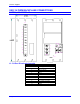
Hardware Connection
In this technique, the rotor (armature) current is commanded by PMAC2 phases A and C. The motor
armature leads should be connected between the two half-bridges of the amplifier driven by PMAC2
phases A and C, together forming a full H-bridge.
The armature current sensor should feed an A/D converter that is connected to one of the serial ADC
inputs for the channel on PMAC2. If there is a wound field, the armature current reading must be fed into
ADC A and the field current reading must be fed into ADC B.
If there is a permanent magnet field only, the armature current reading can be fed into either ADC A or
ADC B, with Ix82 telling PMAC2 which one is used. If ADC A is used, the serial digital input for ADC
B (+signal only) should be tied to GND so a zero feedback value is forced (alternately a background PLC
can zero the direct current integrator register periodically). If ADC B is used, then PMAC uses the
Compare A read/write register for the (non-existent) direct current feedback; in this case, a zero value
should be written into this register on power-on/reset, and no other value should be written to it during the
application.
If there is a wound field, it must be commanded from PMAC2’s B phase, and the current feedback must
be brought back into PMAC2’s B-phase. If only uni-directional voltage and current are required for the
field, the field windings can be commanded from a single half-bridge. If bi-directional voltage or current
is required, a full H-bridge must be used, with PMAC2’s B-phase commanding the two half bridges in
anti-phase mode (also the command for the top of one half is used for the bottom of the other half).
I-Variable Setup
To set up a motor for this technique, the following I-variable settings must be made:
Ix00 = 1 to activate the motor •
•
•
•
Ix01 = 1 to activate commutation algorithms
Ix02 should contain the address of the PWM A register for the output channel used (this is the
default), just as for brushless motors
Ix70 = 4, Ix71 = 4: This defines a commutation cycle size of 4/4 = 1 count. The use of 4/4 instead of
1/1 allows us to rotate the angle +
90
o
for test and tuning purposes.
Ix72 = 64 or 192 for 1/4 or 3/4 cycle between the armature (rotor) and field (stator). If a positive
voltage output number creates a negative current feedback number, use 64; otherwise use 192.
•
•
•
•
Ix73 = 0, Ix74 = 0: No power-on phase search will be required
Ix75 = 0: Zero offset in the power-on phase reference
Ix77 = 0 for motors without wound field. With a wound field, Ix77 determines the strength of the
field; with field weakening functionality, Ix77 will be a function of motor speed.
Controller Setup 29