
User manual


3U Servo Amplifier
Wiring the Motor Thermostats
Some motor manufacturers provide the motors with integrated thermostat overload detection capability.
Typically, it is in one or two forms: a contact switch that is normally closed or a PTC. These sensors can
be wired into the Geo drive's front panel MTR TEMPERATURE SWITCH. Motor 1 thermostat is wired
to MTR1 PTC RET and MTR1 PTC. And Motor 2 thermostat can be wired to MTR2 PTC RET and
MTR2 PTC. These contacts have to be low impedance for the drive to be operational.
If the motor overload protection is not required, these pins (MTR1 PTC and MTR1 PTC RET, MTR2
PTC and MTR2 PTC RET) should have the jumpers ON (default) so as to disable this function in the
drive. Otherwise, the drive status display will show immediately an error code “1E6” for motor #1 over
temperature or a “2E6” for motor #2 over temperature.
When the motor over temperature error code is tripped, the drive will immediately write a value of “06”
at the ADC A register for the axis on the PMAC, bits 11:4. It is recommended that the user writes a
special PLC, so as to react accordingly to this error code. After 60 seconds in this condition, the amplifier
will fault and motion will stop. The seven-segment display will change the fault code from “1E6” or
“2E6” to “1F6” for motor #1 and “2F6” for motor #2.
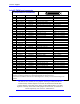
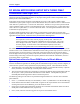
Motor Temperature Switch
Pin Symbol Function
1 MTR1_PTC Input
2 MTR1_PTC_RETURN Input
If motor does not have overtemp sensor output
must jump pin 1 to pin 2 (as sent from factory)
3 MTR2_PTC Input
4 MTR2_PTC_RETURN Input
If motor does not have overtemp sensor output
must jump pin 3 to pin 4 (as sent from factory)
Note: If the input is not used, then a regular jumper can be used.
4-pin Molex Connector .100 spacing, 22-28AWG
DeltaTau p/n: 200-000R04-LHM
MOLEX p/n: 22-01-3047(housing), 08-50-0114(pins)
Backplane Board 24